WhatsApp
 jessica.chai@ltzzc.com
 0086-379-69950051

How a Three Row Roller Slewing Bearing Splits Loads
How can one bearing support radial force, axial force, and a large tilting moment without forcing every rolling element to carry every load at once? The answer is load separation. A Three Row Roller Slewing Bearing uses separate roller paths so that radial loading and axial loading are directed into different raceways.
For engineers specifying cranes, ship equipment, large turntables, mining machines, and other heavy duty rotation systems, this layout can provide high capacity within a limited bearing diameter. The benefit is not simply “more rollers.” It is the ability to assign each load direction to a raceway built to carry it.
At the early specification stage, compare the duty cycle, mounting structure, radial force, thrust direction, overturning moment, gear torque, and installation space before selecting a bearing type. LTZC offers precision slewing bearing solutions for demanding rotational equipment, including custom designs based on working conditions, existing drawings, and technical requirements.
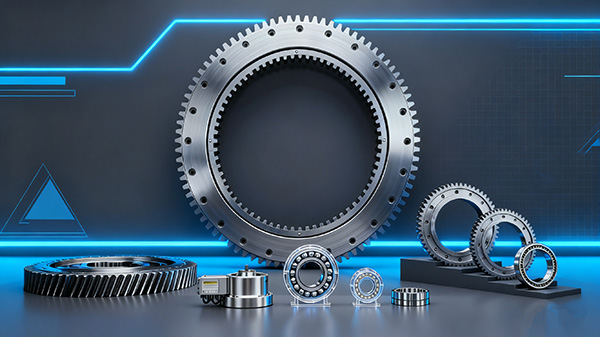
Why load separation raises usable capacity
A three row arrangement normally contains one roller path intended mainly for radial force and two roller paths intended mainly for axial force. The upper and lower axial rows work from opposite sides of the bearing structure. Together, they resist axial force in either direction and generate the reaction couple needed to resist overturning moment.
The design conclusion is straightforward: choose this arrangement when the machine applies significant combined loads and the bearing must remain within a restricted outer diameter. Separating the load paths allows each roller row to work under a more defined loading condition than a bearing where a smaller number of contact paths must accept radial force, thrust, and moment simultaneously.
This is particularly suitable for large lifting structures, heavy excavating equipment, stacker reclaimers, marine handling systems, and large diameter turntables. For example, a crane upper structure may impose downward vertical load, horizontal radial load from motion or wind, and a high overturning moment from an offset boom. In such a case, a dedicated radial roller row can support radial force while the opposing axial rows manage thrust and moment reactions.
It does not automatically make this layout the best option for every rotating machine. If loads are modest, space is limited in the axial direction, or rotation accuracy at a smaller diameter is the leading requirement, another type may be more appropriate. A Cross Roller Slewing Bearings design, for example, may suit applications with different space and accuracy priorities.
Before selecting a bearing family, use a bearing selection guide to organize the application inputs. A bearing supplier cannot make a sound load assessment from outer diameter alone.
Comparison of the separate radial, axial, and overturning-moment roller paths and how each raceway carries load
The following table shows what each load path does in practice. The overturning moment is resisted by the two axial roller paths acting as a pair; it is not usually carried by the radial row alone.
| Load path | Primary raceway role | What happens in operation | What goes wrong if specified incorrectly |
|---|---|---|---|
| Radial load path | The radial roller row carries force directed toward or away from the bearing center. | It supports side loads created by horizontal movement, gear mesh force, structural offset, or equipment travel. | If radial load is underestimated, roller contact and raceway stress can rise beyond the intended condition. The bearing may show uneven running, localized wear, or reduced service life. |
| Upper axial load path | The upper axial roller row carries thrust acting from one mounting side toward the other. | Under a tilting load, this row may become the compression side of the moment reaction pair. | If the load direction is misunderstood, the selected internal arrangement may not provide suitable margin under the actual lifting or overturning condition. |
| Lower axial load path | The lower axial roller row carries thrust in the opposite direction. | It becomes the compression side when the overturning direction reverses, such as during boom movement, braking, or changing payload position. | If the machine frequently reverses moment direction but the duty data show only one condition, the bearing assessment can miss a major operating case. |
| Overturning moment load | The two axial raceways act together through their separation within the bearing section. | One axial row carries increased compression while the opposite row provides the matching reaction as the structure attempts to tilt. | If moment is calculated from load alone without its lever arm, the bearing may be selected for thrust but not for the actual tilting demand. |
For design engineers, the key distinction is that radial load and axial load should not be treated as interchangeable inputs. Radial force acts across the bearing diameter. Axial force pushes through the bearing axis. Overturning moment tries to rotate one ring relative to the other around a horizontal axis, increasing load on one axial row and changing the contact condition on the other.
A useful specification package identifies the maximum load in each direction, the direction of each load, the position where it acts, and whether the operating condition reverses. This information lets the bearing manufacturer examine bearing load distribution rather than relying on a single combined force value.
How to decide whether this bearing arrangement fits the machine
Use a three row arrangement when the application has high combined load, a large moment arm, and a need to keep the bearing diameter under control. It is often a practical choice for equipment that must rotate a heavy upper structure while carrying loads offset from the centerline.
The following decision checklist helps engineering teams identify whether this is the right starting point.
- Confirm all load directions. Provide radial force, axial force, and overturning moment separately. This fits equipment with multiple force directions. It does not apply when only a simple static vertical load is known and the rest of the operating duty remains undefined.
- Include the worst load position. Assess the maximum reach, maximum payload position, braking condition, and any eccentric tooling position. A central load may look acceptable while an offset load produces a much larger moment.
- Record moment reversal. Determine whether the machine changes rotation direction, boom position, payload side, or operating angle. This is needed where upper and lower axial rows alternate as the higher loaded row.
- Check the mounting rings. The bearing transfers force into the machine frame. A suitable bearing cannot compensate for a weak, distorted, or uneven mounting surface.
- Review gear loading separately. If the bearing has integral gearing, include pinion force, gear torque, duty cycle, and backlash requirements. The raceway selection and gear design affect different parts of the assembly.
- State the allowable envelope. Give outer diameter, inner diameter, total height, mounting hole arrangement, and gear position where applicable. This fits early design work; it does not replace a final drawing review.
For a crane application, engineers should compare the bearing with a purpose designed Crane Slewing Bearing configuration. The selection should account for boom position, payload position, slewing torque, and mounting structure rather than relying only on machine tonnage.
Specify the raceway system before fixing diameter
A frequent early-stage mistake is to begin with a preferred outside diameter and then attempt to fit all loads into that envelope. Start with the load system instead. The internal arrangement, roller size, roller count, raceway geometry, ring section, and mounting interface must work together.
Use this step-by-step procedure when preparing a request for quotation or a technical review.
- Define the rotating member. Identify what rotates, where its center of gravity sits, and which components create offset force.
- List operating conditions. Separate normal operation, maximum load, startup, braking, emergency stop, transport, and maintenance positions where relevant.
- Calculate applied forces. Submit radial load, axial load capacity requirements, overturning moment load, and gear forces as separate entries.
- Identify load direction. Show whether each load is upward, downward, inward, outward, continuous, intermittent, or reversing.
- Provide interface drawings. Include mounting surfaces, bolt circles, ring support width, gear location, drive location, and clearance limits.
- State environmental conditions. Include contamination exposure, corrosion exposure, temperature conditions, lubrication method, and accessibility for maintenance.
- Request a matched design review. Ask the supplier to confirm the raceway arrangement, material proposal, gear option, and mounting requirements against the submitted operating data.
This sequence is suitable for a new machine design or a replacement where the duty is changing. It is less useful when the goal is only to duplicate an existing bearing without any drawing, part marking, or operating history. In that situation, first identify the existing bearing dimensions and internal construction.
Common specification mistakes that reduce bearing life
Three row designs manage demanding combined loads well when the applied forces reach the intended raceways. The following mistakes can defeat that advantage.
| Common mistake | Practical consequence | Correct action |
|---|---|---|
| Combining all forces into one simplified load figure | The supplier cannot see whether radial load, thrust, or moment controls the design. | Submit a load table with each force direction and moment condition listed separately. |
| Ignoring load reversals | The opposite axial row may become highly loaded during a condition not included in the review. | Show reversing travel, changing boom position, braking, and alternating payload locations. |
| Using an unsupported mounting frame | Ring distortion can alter roller contact and produce uneven loading around the raceway. | Review mounting surface flatness, ring support width, stiffness, and bolt arrangement with the bearing supplier. |
| Focusing only on bearing diameter | A large diameter alone does not confirm that the raceway system fits the applied load pattern. | Assess the internal roller arrangement and mounting interface before approving the envelope. |
| Leaving gear loads out of the request | Pinion force and gear torque may be omitted from the total radial loading condition. | Provide drive layout, gear location, torque direction, and operating duty for geared rings. |
| Planning lubrication and inspection too late | Maintenance access may be restricted after installation. | Locate grease points and inspection access during the equipment layout stage. |
Installation also matters after the bearing is delivered. LTZC provides bearing installation guidance, preventive maintenance training, fault diagnosis, and on-site technical assistance. For quality objections, LTZC states a response within 24 hours, with on-site service beginning within 48 hours in China.
Use proven manufacturing capability as part of the selection review
For large rotation systems, bearing selection is not only a calculation exercise. The supplier must be able to manufacture the required ring construction, raceways, roller arrangement, gear features, and custom interface. LTZC has operated since 1992 from a 20,000 m² facility and holds ISO9001:2015, ISO14001:2015, and ISO45001:2018 certifications, as well as ISO, CCS, and ABS certification stated by the company.
Material selection should follow the actual duty. LTZC works with materials including GCr15 for hardness, wear resistance, and strength in roller and ball bearings; 20CrMo and 42CrMo for increased strength, hardness, and wear resistance in heavy load bearing applications; and AISI 440C where corrosion and oxidation resistance are required. Material choice alone does not solve a loading problem. It must match raceway design, lubrication, environment, and the complete bearing structure.
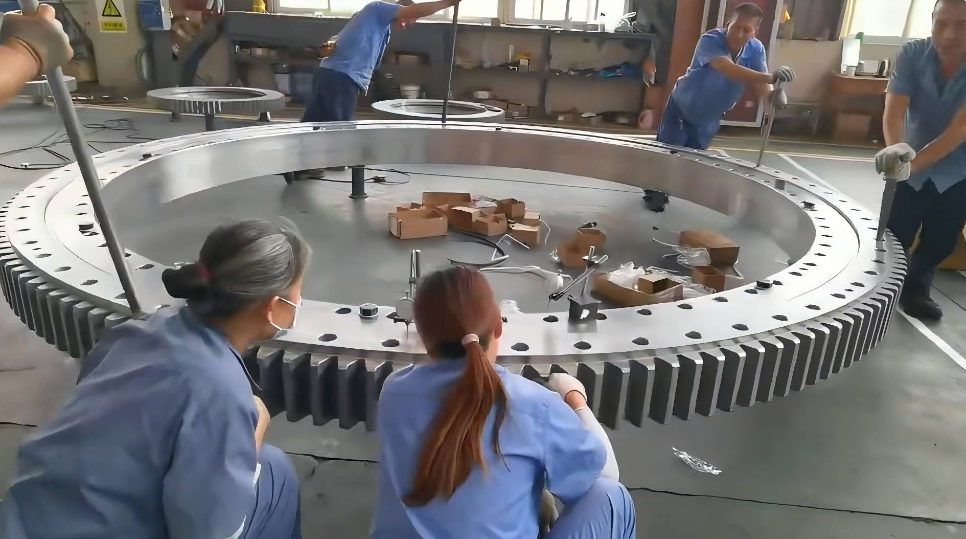
LTZC has delivered large bearing solutions that demonstrate relevant scale. In 2024, the company delivered an integral three row roller slewing ring with an outer diameter of 10.87 meters for 2,000 ton fixed lifting equipment. In the same year, LTZC produced an integrated bearing with an outer diameter of 8.445 meters for a crane industry client in South Korea. These cases show production experience with large bearing structures, but they should not be treated as a rating for a different machine. Each application still requires its own load review.
LTZC also offers custom bearing solutions without a stated minimum order quantity and with stated delivery of 30 to 90 days. Lead time depends on the bearing design, material, manufacturing route, and order requirements; it should be confirmed for each project rather than assumed from a general range.
Match the bearing choice to the full rotation assembly
The bearing is one part of the rotation system. The drive, gear, mounting structure, lubrication arrangement, and control of operating loads all influence the final result. Where a compact drive package is needed, review compatible Slewing Drives alongside the bearing design. Where integral teeth are part of the requirement, the slewing ring gear arrangement should be assessed for torque direction, pinion engagement, and access for inspection.
The clearest selection rule is this: select a three row roller arrangement when separated radial and axial load paths solve a real combined-load problem. Do not select it only because the machine is large. A correctly defined load table, a stable mounting structure, and a supplier review of the actual duty are the basis for a dependable result.
Submit your load table and mounting drawings to LTZC for bearing selection advice.