WhatsApp
 jessica.chai@ltzzc.com
 0086-379-69950051

How an Excavator Slewing Bearing Carries Swing Loads
What carries the bucket load when an excavator swings: the bearing, the bolts, the gear, or the upper structure? The answer is all of them, but each component has a different job. An Excavator Slewing Bearing carries vertical weight, side force, and overturning moment through a controlled load path between the upper carriage and undercarriage. The swing gear supplies rotation torque, while the mounting bolts keep the complete joint clamped and aligned.
For maintenance engineers, this distinction matters when diagnosing uneven rotation, abnormal grease discharge, loose fasteners, tooth wear, or raceway damage. For equipment buyers, it matters before specifying a replacement unit. A bearing selected only by outside diameter, bolt count, or tooth module can fit physically yet fail early because the real duty includes a heavier attachment, an extended boom position, repeated side loading, or poor mounting flatness.
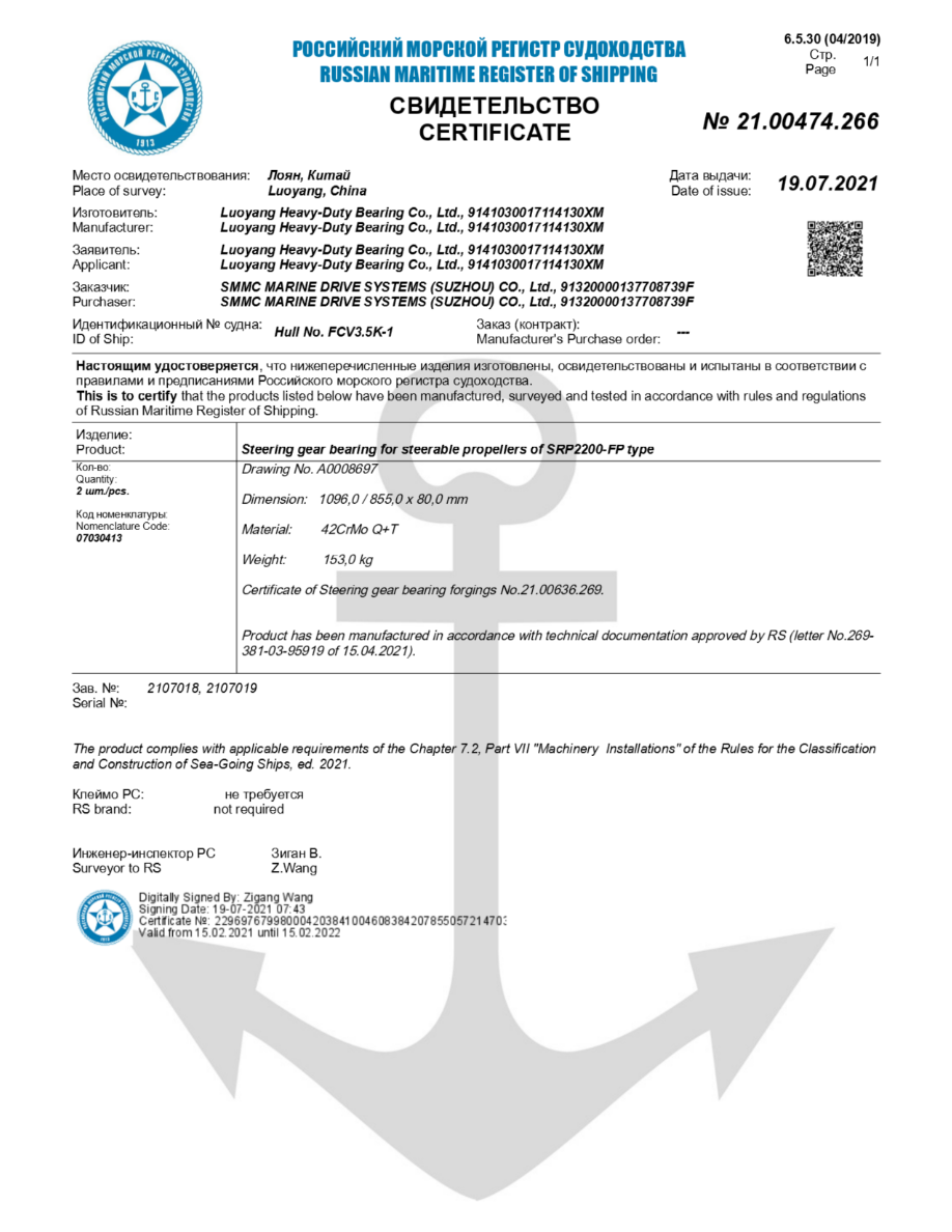
The bearing is not a stand-alone component. It operates as part of a structural system formed by the upper frame, lower frame, mounting bolts, gear drive, lubrication arrangement, and working attachment. A sound replacement decision begins with the load path rather than the catalog dimensions.
Identify the loads created during digging and swinging
An excavator swing system is exposed to more than the static mass of the upper structure. The boom, arm, bucket, payload, hydraulic forces, slope angle, travel position, and swing acceleration all change the force arriving at the turntable. The most demanding condition is often not a full bucket at the machine centerline. It may be a loaded bucket held far from the swing axis while the operator starts, stops, or reverses rotation.
Conclusion: define the duty by the worst operating position and motion, not by machine class alone. This approach fits replacement projects where the original application has changed, such as a different boom arrangement, demolition tool, material handler attachment, or modified counterweight. It does not replace a machine-level structural review where the upper and lower frames themselves may have been altered or damaged.
| Load type | What creates it | What it affects in practice | Risk when underestimated |
|---|---|---|---|
| Axial load | Upper structure weight, attachment weight, payload, and downward digging reactions | Rolling element contact on the loaded raceway zones and compression across the mounting joint | Raceway indentation, uneven rotation, and increased resistance to swing |
| Radial load | Side digging, slewing on a slope, lateral attachment force, and frame deflection | Side contact between rolling elements and raceways, plus local bolt and housing reactions | Edge loading, cage or separator distress where fitted, and poor gear mesh alignment |
| Overturning moment | Load held away from the bearing center, boom outreach, attachment leverage, and braking forces | Alternating high and low load zones around the bearing circumference | Localized raceway fatigue, bolt unloading, structural movement, and premature bearing failure |
| Drive torque | Swing motor output transmitted through pinion teeth | Gear tooth contact, pinion support, and local tangential force at the geared ring | Tooth wear, backlash changes, cracked teeth, or erratic swing movement |
Axial force is often called thrust load. It acts along the vertical axis of the swing system. Radial force acts sideways through the center of the ring. Overturning moment is different: it is a force multiplied by distance from the center. A modest force at a long reach can create a large moment, shifting a substantial share of the rolling elements into a heavily loaded sector.
Do not assume a bearing sees one uniform load around its full circumference. During a high outreach lift, one zone may carry most of the contact stress while the opposite zone may experience reduced loading. When the machine repeatedly works in the same direction, localized wear can appear in a recurring arc rather than around the complete ring.
Before comparing replacement options, review the machine’s attachment, maximum working radius, usual material density, swing habits, and operating surface. The bearing selection guide can help organize those inputs before a drawing or technical request is issued.
Compare axial, radial, and overturning moment load paths
The following comparison shows how each load travels through the raceways, rolling elements, mounting bolts, and gear. The gear should not be treated as the primary vertical support. Its main role is to transmit rotational torque. However, gear position and mesh accuracy can be affected when the bearing, bolts, or mounting faces permit unwanted movement.
| Load path element | Axial load path | Radial load path | Overturning moment load path |
|---|---|---|---|
| Raceways | Opposing raceway surfaces transfer vertical force through their loaded contact zones. | Raceway geometry resists side movement and keeps the upper and lower rings centered. | One side of the ring develops higher contact force while the opposite side unloads or carries less force. |
| Rolling elements | Balls or rollers transfer compressive force between the upper and lower rings. | They react lateral force according to bearing geometry and clearance condition. | They concentrate load in sectors; repeated peak loading can damage a limited arc of the raceway. |
| Mounting bolts | Preload holds the bearing rings tightly against both mounting faces so joint compression remains stable. | Bolts and the clamped interfaces help prevent ring shift relative to the structure. | Bolts near the high moment zone may see increased demand while bolts on the opposite side can lose effective clamp load. |
| Gear | The gear does not normally carry the main vertical machine load. | Misalignment caused by radial movement can alter pinion tooth contact. | Ring tilt or frame deflection can change mesh position and concentrate tooth contact during swing. |
Conclusion: specify the bearing, bolts, and mounting structure as one interface. This is appropriate for any replacement bearing assessment because a correctly sized ring can still be damaged by loose bolts, unsupported areas, distorted mounting faces, or incorrect gear mesh. The limitation is that a bearing supplier cannot verify the full machine frame capacity without accurate structural information from the equipment owner or manufacturer.
What happens when the load path is interrupted
Insufficient mounting bolt preload: the rings can move microscopically against the mounting faces. This movement may reduce stiffness, change raceway loading, and allow bolt fatigue conditions to develop. Use the specified tightening procedure and controlled sequence; do not rely on impact tightening alone.
Uneven mounting support: a high spot or distorted face can force the ring to conform during tightening. The raceway may then operate out of its intended geometry. Inspect the mounting surfaces before installation, especially after welding repair or frame damage.
Excessive internal clearance: the upper structure can rock more under moment load. Gear mesh may vary around the circumference. This condition should be assessed against the bearing design and machine service requirements rather than judged by feel alone.
Incorrect pinion engagement: tooth contact can become concentrated at one part of the gear tooth. The bearing may still turn, but the drive system can generate noise, tooth damage, and irregular swing motion.
Repeated one-direction loading: the same raceway arc carries peak force repeatedly. Rotate working patterns where practical, and inspect the expected loaded zone during planned maintenance.
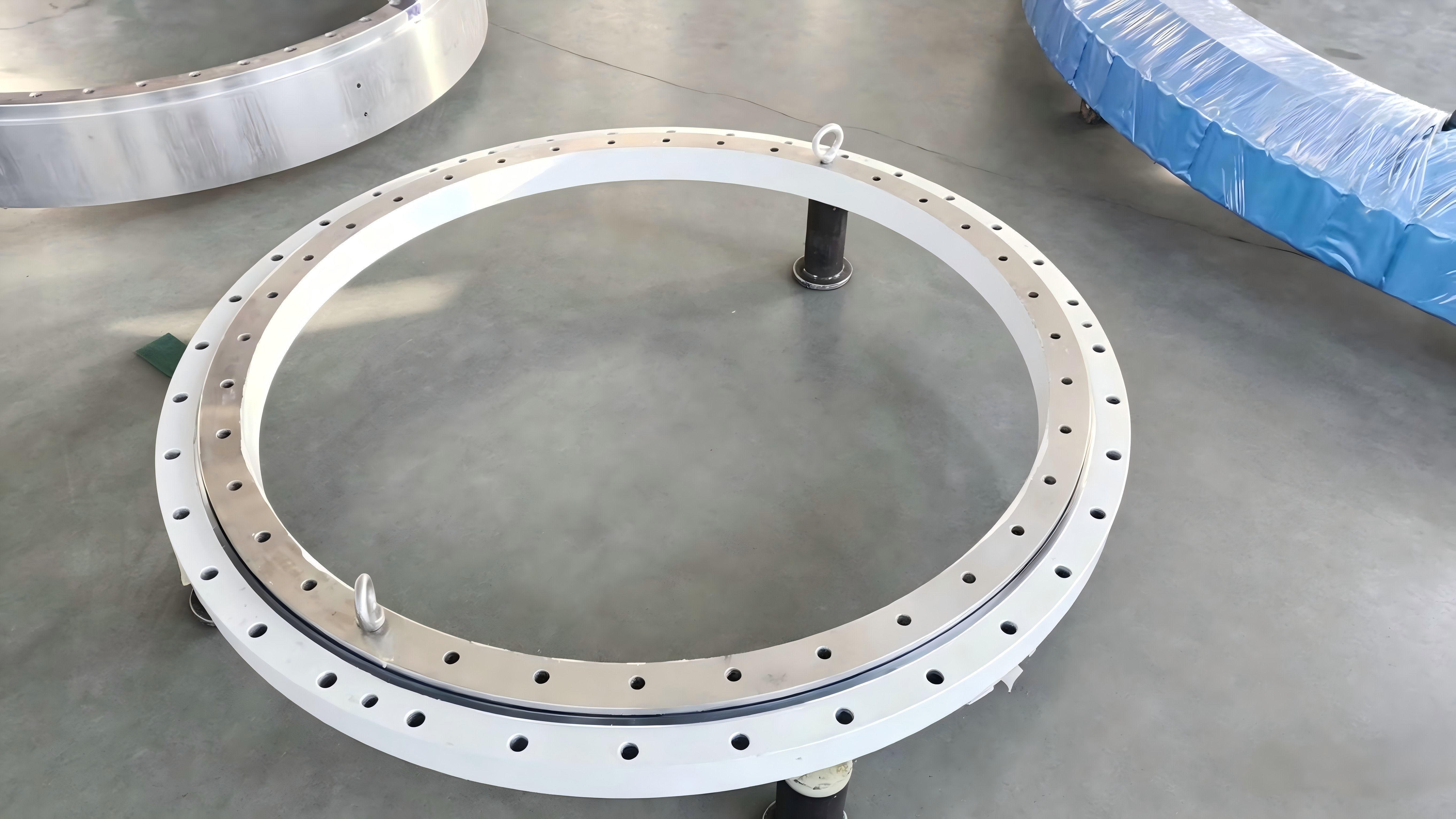
Choose bearing geometry for the actual duty cycle
Excavator applications commonly use slewing ring arrangements designed to carry combined loads. The best geometry depends on the required load capacity, available installation space, gear location, bolt pattern, rotational accuracy, and service conditions. Replacement selection should begin with the existing drawing and operating requirement, not with a photo alone.
Conclusion: retain the original functional geometry unless the duty has changed or a qualified engineering review supports a redesign. This fits a direct replacement where the machine structure, attachment, gear drive, and mounting arrangement remain unchanged. It does not apply when the original bearing has failed because the application was modified or the original selection no longer matches the work cycle.
| Selection input | Why it matters | Immediate buyer action | Limit of the input |
|---|---|---|---|
| Ring dimensions | They establish physical fit within the swing platform. | Provide outside diameter, inside diameter, height, and gear location from the current part or drawing. | Dimensions alone do not confirm load capacity. |
| Bolt pattern | It connects the ring to the upper and lower structures. | Confirm bolt quantity, thread form, spacing pattern, and mounting hole arrangement. | A matching pattern does not prove correct bolt preload or frame condition. |
| Gear details | They determine pinion compatibility and torque transfer. | Confirm internal or external gear arrangement and provide tooth data where available. | Gear data does not describe vertical or moment load. |
| Attachment duty | It changes axial force, side force, and moment demand. | State the attachment type, material handled, working radius, and usual work cycle. | Duty descriptions must be realistic; nominal machine size is not enough. |
| Operating environment | Contamination, temperature, and moisture affect sealing and lubrication needs. | Describe exposure to dust, water, abrasive material, and storage conditions. | Environmental information does not replace proper installation control. |
At LTZC Bearings Co., Ltd., we provide customized bearing solutions based on working conditions, existing designs, and technical specifications. This is useful when the replacement must match nonstandard dimensions, a particular gear arrangement, or application-specific performance needs. Our scope includes precision slewing bearing options, gear rings, flanges, slewing drives, and related bearing parts.
LTZC operates under ISO9001:2015, ISO14001:2015, and ISO45001:2018 management system certifications and is certified by ISO, CCS, and ABS. These stated qualifications support controlled quality and management processes, but they do not remove the need for the buyer to provide correct application information and installation conditions.
Inspect the mounting interface before blaming the bearing
A replacement bearing cannot correct a distorted or poorly prepared turntable. Before removal, record the existing condition. Look for bolt loosening, grease leakage paths, tooth wear patterns, uneven ring support, cracked structure, and localized damage. These observations help distinguish a bearing issue from a mounting, lubrication, or drive issue.
Conclusion: inspect the complete swing interface before ordering a replacement. This is especially suitable after abnormal noise, increased rocking, recurring gear wear, or a previous early failure. It may not identify hidden internal raceway damage without further inspection, but it can prevent repeating visible installation errors.
Document the current assembly. Photograph the bearing, gear position, pinion contact area, bolt arrangement, grease lines, seals, and identification markings before disassembly.
Measure operating symptoms. Record where rocking, tight rotation, noise, or backlash changes occur around the swing circle. A symptom that occurs at one position can indicate localized loading or damage.
Check bolts and mounting faces. Follow the machine manufacturer’s safety and service procedures. Identify loose, stretched, corroded, or damaged fasteners, then inspect both structural faces for fretting marks, raised metal, cracks, and unsupported areas.
Inspect gear teeth. Examine the full circumference, not one visible section. Compare tooth flanks for uneven polishing, pitting, broken edges, or a changing contact pattern.
Review lubrication evidence. Check grease condition, blocked lines, damaged seals, and areas receiving poor distribution. Lubricant cannot repair overload damage, but insufficient lubrication can speed wear.
Submit technical inputs together. Send the existing drawing or part number, dimensions, bolt pattern, gear details, photographs, attachment information, and fault history in one request.
Use documented installation procedures after replacement. The bearing installation resource is a practical reference for planning the work sequence and maintenance checks. The final tightening values, lubrication intervals, and safety controls must follow the applicable machine and bearing documentation.
Match sourcing requirements to replacement risk
Replacement procurement is often time-sensitive, but speed should not erase technical verification. A buyer should compare the delivery need against the time required to confirm drawings, materials, gear compatibility, mounting details, and requested documentation. LTZC states a delivery range of 30 to 90 days and no minimum order quantity. That can suit one-off replacement requirements as well as planned procurement, subject to the confirmed specification and order conditions.
Conclusion: request a technical confirmation before committing to a replacement bearing. This fits buyers sourcing standard or nonstandard rings where fit, gear engagement, and duty must be checked. It does not mean every application needs a redesign; an unchanged, fully documented original assembly may only need verification against the supplied drawing.
Buyer decision checklist
Confirm the existing bearing drawing, identification details, and all measurable mounting dimensions.
State whether the ring has an internal gear, external gear, or no gear.
Provide the bolt pattern for both mounting interfaces, not only one side.
Describe the attachment and the highest anticipated working radius.
Report whether the machine works on slopes, performs side digging, or makes frequent swing reversals.
Describe the observed failure pattern, including its location around the ring.
Confirm the pinion condition and whether gear teeth show uneven contact.
Specify required documents, inspection expectations, packing needs, and delivery target.
Include clear photographs of the mounting faces and complete bearing assembly.
A technically complete request reduces the chance of receiving a ring that fits the machine but does not suit the load path. It also gives the supplier a better basis for recommending non-standard bearings when the original design needs a tailored solution.
Use load evidence to prevent repeat failures
A failed ring should be treated as evidence, not simply as scrap. Raceway marks, bolt condition, gear tooth contact, seal damage, and the location of rocking can point to the dominant load issue. For example, damage concentrated in one recurring sector may suggest a repeated high outreach working position. Widespread tooth wear with variable mesh may point toward ring movement, frame distortion, or pinion setup concerns.
The practical rule is simple. Axial load pushes through the bearing vertically. Radial load tries to shift the rings sideways. Overturning moment tries to tilt one ring relative to the other. The raceways and rolling elements carry these forces internally; the bolts and mounting faces maintain the joint; the gear transfers turning torque. Each part must be assessed together.
Submit your drawing, operating conditions, and current bearing details to LTZC for replacement selection advice.