WhatsApp
 jessica.chai@ltzzc.com
 0086-379-69950051

Industrial Slewing Bearings Carry Robot Loads Through Defined Force Paths
How does a robot base remain accurate when an arm extends, accelerates, stops, and changes direction? The answer begins with understanding where the load goes after it reaches the rotary joint. Industrial slewing bearings are designed to support combined axial force, radial force, and overturning moment at the same time, but their behavior depends on the complete assembly: the bearing, mounting structures, bolts, gear engagement, drive arrangement, and operating cycle.
For automation engineers at the early evaluation stage, the most useful question is not simply “What bearing diameter is needed?” It is “Which loads act on the bearing raceways, how do they transfer into the robot base, and what design choices can create clearance, distortion, or abnormal wear?” A bearing that fits the envelope may still be the wrong selection if the base plate flexes, the load center is far from the axis, or the mounting bolts cannot retain the ring under moment loading.
Start with the Robot Motion and the Actual Load Cases
Conclusion: Define the complete motion cycle before comparing bearing types. Static payload alone is not enough because robot joints create changing force directions and changing moment arms during rotation.
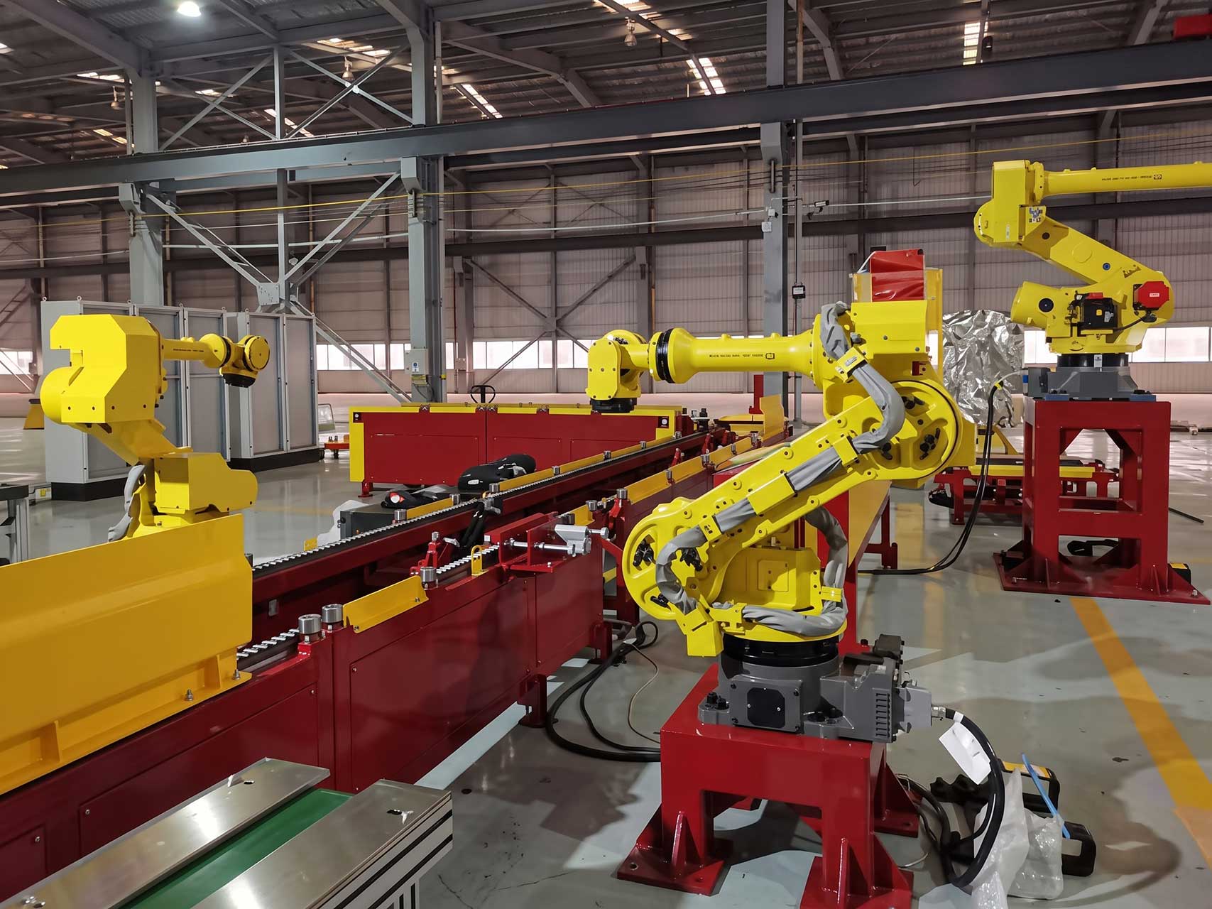
The reasoning is straightforward. A robot base may support the arm and tooling at rest, but during operation it also sees acceleration, deceleration, emergency stops, off center payload positions, cable drag, gear drive forces, and forces transferred from the robot structure. The bearing does not experience one constant value. It sees a range of combined conditions.
This approach fits articulated robots, palletizing cells, welding positioners, inspection platforms, rotary handling stations, and similar equipment where the upper structure rotates relative to a fixed foundation. It does not replace a full structural or dynamic calculation for safety related equipment, high speed systems, or applications with significant impact loading. Those designs require the machine builder to evaluate the entire load system.
Build a load case list before requesting a bearing quotation
Parked condition: Identify the arm position that places the payload farthest from the rotation center. This often creates the highest overturning moment load.
Maximum reach condition: Record the combined mass of arm sections, end effector, workpiece, fixtures, and any attached process equipment.
Acceleration condition: Include forces generated when the rotating assembly starts or changes speed. The drive torque required by the motion system can affect gear and ring loading.
Deceleration condition: Consider braking direction separately. A reversal can move contact from one raceway zone to another.
Process condition: Include external forces such as welding cable pull, dispensing hose pull, machining force, or contact forces from handling equipment.
Transport or maintenance condition: Check whether the machine is moved, tilted, lifted, or locked in a position that differs from its normal operating posture.
A useful RFQ package states the rotating mass, center of gravity location, vertical and horizontal forces, overturning moments, rotational speed, duty cycle, mounting arrangement, and available installation space. A bearing selection guide can help organize these inputs, but the final selection should be based on the actual machine load cases rather than a general payload rating.
Load Path Breakdown for a Robot Base Slewing Bearing
Conclusion: Treat axial, radial, and moment loads as connected forces rather than isolated catalog entries. Each load enters the bearing differently, passes through different contact zones, and places different demands on the rings, raceways, rolling elements, bolts, and support structures.
The table below explains what each force does in practice. It also shows what can happen when the load path is misunderstood during early design.
| Load type | Typical robot source | Transfer path through the assembly | What the parameter affects | What can go wrong if underestimated |
|---|---|---|---|---|
| Axial load | Weight of the rotating arm, payload, upper frame, and tooling | Upper structure → rotating bearing ring → rolling elements and raceways → stationary ring → base frame or foundation | Raceway contact loading, vertical deflection, contact distribution, and the load carried by mounting interfaces | Excessive settling, increased internal clearance, poor repeatability, local raceway stress, or reduced bearing service life |
| Radial load | Horizontal process force, side pull from cables, belt forces, gear mesh forces, or off axis interaction with equipment | Side force at upper structure → ring body → rolling element contact zone around the bearing circumference → lower ring → base structure | Radial positioning, ring deformation, side movement, and the relationship between bearing alignment and gear engagement | Uneven contact, rotation resistance, gear tooth contact problems, abnormal wear, or reduced positioning accuracy |
| Overturning moment | Extended arm mass and payload acting at a distance from the rotation axis | Offset load → upper mounting face → one side of bearing carries higher compression while the opposite side tends toward separation → bolts and base structure resist ring lift and distortion | Contact concentration, bolt retention, ring stiffness, support flatness, and tilt at the robot base | Ring rocking, mounting bolt loosening, local overload, uneven raceway wear, or loss of robot end effector accuracy |
Axial load capacity matters most when the upper structure weight is high and predominantly vertical. It does not by itself confirm suitability for a long reach robot arm. A robot can have moderate vertical weight yet generate a demanding moment because the center of gravity is far from the bearing axis.
Radial load transfer becomes more important where the robot performs lateral processing, where cables pull consistently in one direction, or where the bearing also supports a drive arrangement with gear mesh forces. It is less dominant in a carefully balanced vertical axis with minimal side loading, but it should not be ignored simply because the main payload is vertical.
The overturning moment load is commonly the deciding condition for a robot base. The farther the center of gravity lies from the rotation center, the more strongly the upper structure tries to tilt the rotating ring. On one side of the bearing, rolling contacts carry greater compression. On the other side, the ring may tend to lift away from its support. That tendency is resisted by the bearing design, the mounting bolts, and the stiffness of the mating structures.
A practical design review should therefore trace the path beyond the bearing itself. Ask where force enters the upper ring, where it leaves the lower ring, and whether either mounting face can bend locally. If the supporting flange deflects, bearing capacity listed under ideal support conditions may not represent behavior in the assembled robot.
Select the Bearing Arrangement Around the Dominant Failure Risk
Conclusion: Choose the bearing arrangement according to the load combination and required rotational behavior, not by outside diameter alone. A larger envelope may help, but ring section, rolling element arrangement, raceway geometry, mounting support, and gearing all influence the result.
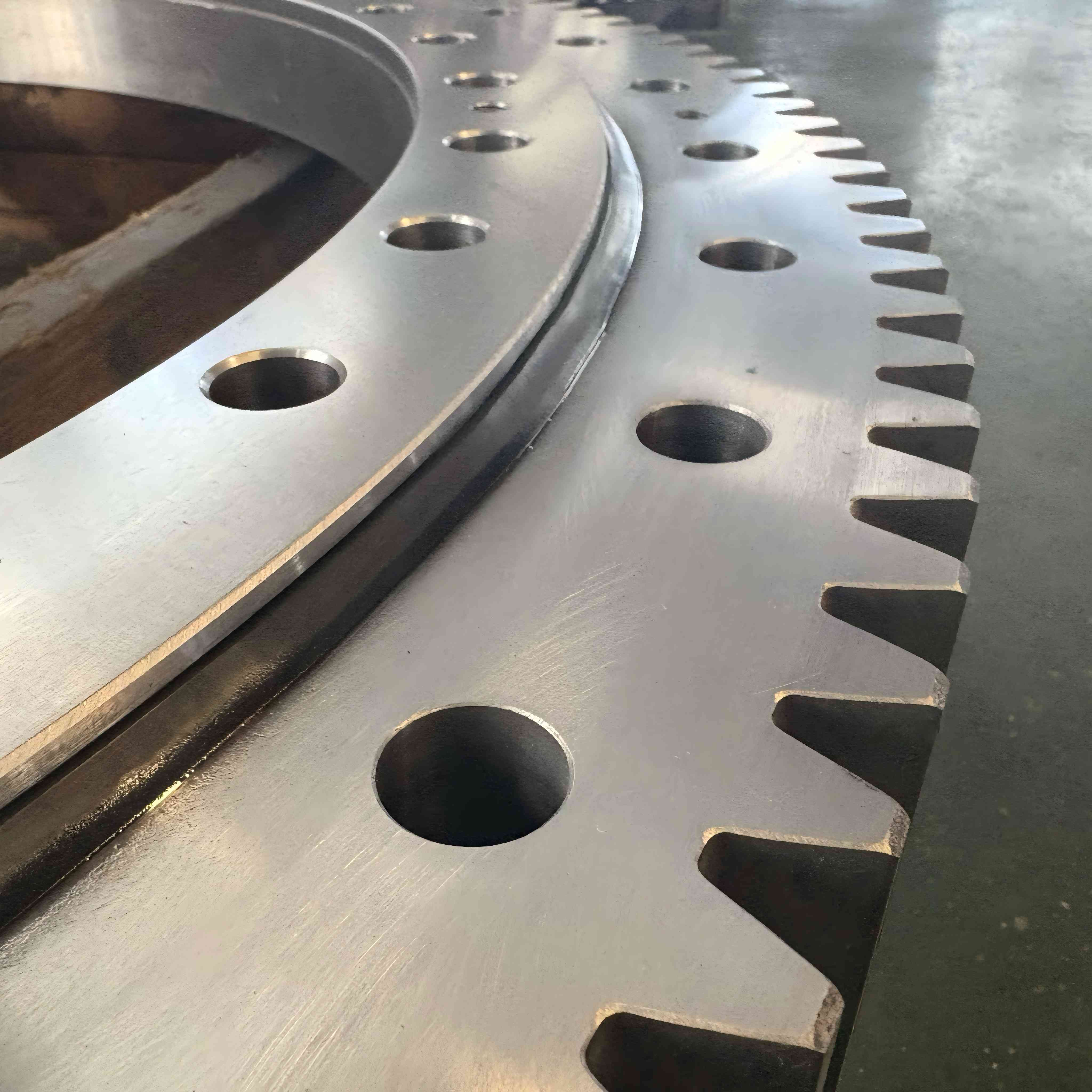
For a robot base that sees substantial axial force and overturning moment, a slewing bearing arrangement is often considered because it combines load support and rotation in one assembly. Where the designer needs a low profile rotating joint and the load level is suitable, a thin section bearing may be assessed as part of a different machine architecture. These options should not be treated as interchangeable. The correct choice depends on the load path, available support diameter, stiffness target, and drive layout.
| Design situation | Selection focus | Why it fits | Limit or caution |
|---|---|---|---|
| Long reach robot arm with offset payload | Moment resistance and mounting rigidity | The extended center of gravity produces tilt demand at the base | Increasing bearing size alone will not correct a flexible base plate |
| Vertical rotary table with centered fixture | Axial support and rotational smoothness | The main load acts close to the rotation axis | Check radial loads from tooling, cable routing, and drive forces |
| Process station with side contact force | Radial load path and structural alignment | Horizontal force can shift contact zones and affect gear mesh | Do not rely on payload mass alone when calculating demand |
| Compact joint with limited axial height | Profile, support diameter, and ring stiffness | The mechanical envelope limits the available bearing cross section | A compact bearing needs equally careful support surface design |
When a gear is integrated into the rotating system, evaluate the gear as part of the load system rather than as a separate procurement item. Gear mesh force adds radial demand, while pinion placement can create a local force concentration. For equipment requiring an external tooth arrangement, the interface between the bearing and slewing ring gear should be reviewed with the drive torque, gear position, backlash requirements, and housing stiffness in mind.
For designs using a self contained rotary drive arrangement, Slewing Drives may suit applications where the drive and bearing functions are specified as a matched assembly. This option does not remove the need to check foundation stiffness or external load directions. The mounting surface still determines how well the assembly can retain alignment under service loads.
Prevent Ring Distortion Through Mounting Design and Installation Control
Conclusion: A correctly selected bearing can still perform poorly if it is mounted on uneven, weak, or poorly supported faces. Treat the base and rotating platform as functional parts of the bearing system.
The reasoning is that a slewing ring is intended to distribute load around its raceways. If the mating structure has local high spots, gaps, weld distortion, or insufficient stiffness, the ring may be forced out of its intended shape during bolt tightening or operation. That alters contact distribution. The result can be higher localized loading even where the calculated external load appears acceptable.
This recommendation applies to welded robot pedestals, fabricated machine frames, machined flanges, turntables, and base plates. It is especially relevant when the upper robot structure is tall or when the bearing has a large support diameter. It does not mean every mounting structure must use the same design. The required support design depends on the actual load cases and the bearing supplier’s installation requirements.
Mounting checks that should appear on the design review
Define which ring is stationary and which ring rotates, then locate all external forces relative to those rings.
Provide continuous and sufficiently stiff support beneath the mounting faces according to the bearing design and machine loading.
Check that bolt locations, accessible tightening space, and service access are included before finalizing the housing.
Review the effect of welded construction, machining sequence, and coating buildup on mounting face condition.
Consider pinion location and gear mesh loading if the bearing includes external or internal gearing.
Set an installation and inspection plan for bolt tightening, lubrication where applicable, rotation checks, and periodic condition review.
Bearings should be installed according to the supplier’s documented instructions for the selected design. LTZC provides guidance for bearing installation, which is useful when planning the assembly sequence and maintenance access. General installation advice should not override machine specific engineering requirements, particularly where the robot is subject to safety standards or exceptional process loads.
Use Preload and Clearance Decisions to Protect Positioning Accuracy
Conclusion: Specify internal clearance or slewing bearing preload according to the required motion behavior and real operating conditions. Excess clearance can reduce repeatability, while excessive preload can increase rotation resistance and contact stress.
In a robot base, clearance can appear at the end effector as small angular movement around the vertical axis. That effect becomes more visible as the arm reaches outward. If the application involves vision inspection, accurate part placement, welding paths, or tool alignment, the designer should assess allowable angular movement at the bearing together with arm deflection and gearbox behavior.
Preload can improve stiffness in some arrangements by reducing free movement between rolling elements and raceways. However, it is not automatically the correct answer. A preload level that is unsuitable for the mounting condition, operating temperature, or load cycle may create higher friction and less favorable contact conditions. Use this approach where positioning stiffness is a defined engineering requirement, not as a blanket response to every clearance concern.
Use clearance evaluation when the system has moderate positioning demands and the major concern is reliable rotation under the expected load range.
Evaluate preload when angular stiffness and motion repeatability are primary requirements and the complete structure can maintain the intended geometry.
Review drive backlash separately because a well supported bearing cannot eliminate position error originating in gears, reducers, couplings, or control tuning.
Review the full arm structure because end effector movement can come from arm bending, joints, fixtures, and foundation movement as well as the bearing.
Prepare a Technical RFQ That Allows a Meaningful Bearing Review
Conclusion: Send load and interface data with the inquiry, not only a requested bearing diameter. This gives the supplier a basis to propose a design that fits the working condition instead of merely matching an existing part number.
LTZC Bearings Co.,Ltd. provides customized bearing solutions based on working conditions, existing designs, and technical specifications. This is useful when a robot base has a nonstandard flange arrangement, a specific gear requirement, limited assembly space, or an existing bearing that needs replacement. The service is not a substitute for the machine builder’s responsibility to define operating loads and safety requirements.
LTZC operates under ISO9001:2015, ISO14001:2015, and ISO45001:2018 systems and is certified by ISO, CCS, and ABS. These are relevant trust signals for buyers assessing supplier management systems. The company also states a delivery range of 30 to 90 days and no MOQ, which can suit both prototype evaluation and production sourcing. Actual delivery should still be confirmed against the selected design, drawing approval status, and order requirements.
Buyer checklist for robot base bearing inquiries
Robot layout drawing showing the bearing position and rotating structure
Maximum rotating mass and center of gravity location
Axial force, radial force, and overturning moment for each major load case
Rotation speed, duty cycle, acceleration pattern, and direction reversals
Required rotational accuracy and allowable system deflection
Gear arrangement, drive torque information, and pinion location where relevant
Mounting bolt pattern, available flange dimensions, and support structure details
Operating environment, including contamination, temperature conditions, and corrosion exposure
Whether the request is a replacement, a new design, or a modification of an existing unit
For a replacement project, provide the existing drawing or measured interface details as well as the reason for replacement. A direct dimensional match may not solve the underlying problem if the original unit experienced bolt loosening, uneven wear, high drive torque, or base distortion. In that situation, the better engineering response is to review the load path and mounting condition before finalizing the replacement.
Submit your robot base drawing and load cases to LTZC for bearing selection advice or a quotation.