WhatsApp
 jessica.chai@ltzzc.com
 0086-379-69950051

How to Match a Cross Roller Slewing Bearing to Turret Loads
Which numbers from a turret design actually determine the size of the bearing under it? Many OEM teams send an RFQ with only an outside diameter and a "radar" label. That is not enough. A Cross Roller Slewing Bearing carries axial load, radial load and tilting moment in a single roller row, so the bearing choice depends on how your turret loads combine, not on any one of them alone.
This guide is for engineers defining a radar, surveillance or rotating platform assembly before the RFQ stage. It shows which inputs to calculate, where each one goes wrong, and when this bearing type is not the right answer.

What a turret asks of the bearing
A turret rarely loads its bearing in a simple way. Gravity pushes down on the raceway, wind or recoil pushes sideways, and any offset in the payload creates a tilting moment that loads one side of the bearing more than the other. The crossed roller arrangement handles all three at once, which is why it suits compact, stiff pedestals.
The conclusion for most turret work is simple: the moment load usually decides the bearing size, not the weight. A light sensor head on a tall mast can load a bearing harder than a heavier head sitting directly on the ring. The reasoning is geometry. Moment grows with lever arm, while weight only adds axial load. This does not hold if the turret is perfectly balanced and sheltered from wind. In that case axial load and rotation life become the main checks.
Turn turret weight, center of gravity offset, duty cycle and positioning accuracy into selection inputs
This is the working procedure we suggest before any bearing is shortlisted. Each step lists the key checkpoint and the usual reason it fails.
| Step | Turret data | Bearing selection input | Checkpoint | Common failure reason |
|---|---|---|---|---|
| 1 | Total rotating mass (payload, structure, cabling, covers) | Axial load Fa = mass × 9.81 | Add the mass above the bearing plane only, but include every accessory | Leaving out de-icing kits, shrouds or cable drums |
| 2 | Center of gravity (CoG) offset from the bearing axis, and height above the raceway plane | Static overturning moment M = Fa × offset | Measure CoG for the real build, including payload extremes | Using the CAD CoG of a bare frame |
| 3 | Wind, dynamic or recoil forces and their height | Radial load Fr and added moment (Fr × height above the raceway) | Use the worst credible case, not the average | Adding radial force but forgetting its moment arm |
| 4 | Duty cycle: continuous rotation, scanning, or small angle oscillation; speed; hours per day | Rotational speed, oscillation angle, starts and stops, torque from inertia (J × angular acceleration) | State whether the turret rotates fully or oscillates over a few degrees | Treating oscillation like slow rotation, which ignores local raceway wear |
| 5 | Positioning accuracy (angular error, pointing stability) | Required clearance or preload condition, mounting stiffness, drive backlash limit | Convert angle to linear error at the working radius | Blaming the bearing for error that comes from the drive or a flexible base |
Step 1 and 2: weight and offset together
Calculate axial load first, then multiply by the horizontal CoG offset. Keep both the static case and the worst case with payload changes. A shifted payload is the most common reason a bearing that looked adequate on paper ends up with a loaded zone concentrated on one side.
Step 3: add external forces with their lever arms
Wind on a radome or antenna face acts at a height above the bearing. Multiply the force by that height and add the result to the offset moment. Skip this and you under-size the bearing, particularly for coastal or exposed sites.
Step 4: define the duty cycle in plain terms
A radar that turns steadily and a surveillance camera that pans back and forth a few degrees stress the raceway differently. Continuous rotation spreads wear around the full track. Small oscillation loads the same rollers repeatedly, so the lubrication film can break down locally. Tell your bearing supplier which case applies, plus start-stop frequency and any emergency braking.
Step 5: convert accuracy into something measurable
A pointing requirement of 0.1° sounds tight, but at a 300 mm working radius it is about 0.5 mm of tangential movement. Ask where that budget goes: bearing clearance, housing flatness, structure flex and gear backlash all share it. The bearing can only take its own part.
A worked example with illustrative numbers
The figures below are illustrative, not a customer case. They show the arithmetic you should bring to an RFQ.
Rotating mass: 1,200 kg, so Fa ≈ 11,772 N.
CoG offset: 150 mm from the axis, so static moment ≈ 11,772 N × 0.15 m ≈ 1,766 N·m.
Wind load: assume 2,000 N acting 0.6 m above the raceway plane, which adds 1,200 N·m.
Total moment to check: about 2,966 N·m, along with Fa and a radial load of 2,000 N.
The takeaway: wind added about 68% to the moment that the weight and offset alone produced. A selection based on the static case would have been undersized. Compare the combined set of axial, radial and moment values to the bearing's rated capacities, and apply the safety factor that fits your duty class and consequence of failure. If the shortlisted bearing only clears the load with no margin, move up a size or change the structure rather than accept a thin margin.
Where a crossed roller design fits, and where it does not
A Cross Roller Slewing Bearing is a strong fit for compact, medium-load, precision rotation. It is not the answer to every turret.
| Option | Best fit | Limits |
|---|---|---|
| Crossed roller single row | Compact pedestals needing stiffness and moment capacity in a small section; pointing and scanning platforms | Heavy shock loads or very large moments may exceed what one roller row can carry |
| Four point contact ball type | Lighter loads, lower cost, moderate moment | Lower stiffness and capacity for the same envelope |
| Three row roller type | Very high moment and axial loads, such as heavy cranes or large antenna mounts | Larger, heavier and costlier; usually more than a light turret needs |
| thin section bearing | Where the envelope is severely limited and loads are light | Moment and shock capacity are limited by the thin cross section |
If you are comparing families, our bearing selection guide covers the wider decision. For loads that outgrow one roller row, a precision slewing bearing in a different configuration may be the better direction.
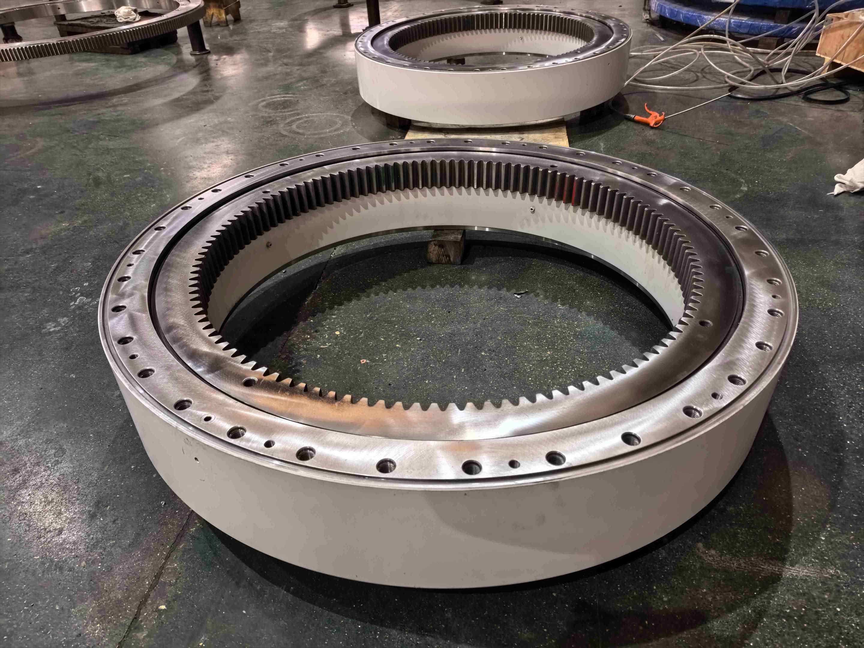
Drive, gear and mounting choices that affect the result
The bearing does not set pointing accuracy alone. A gear ring cut on the bearing, or a worm-driven unit, adds backlash and stiffness of its own. For compact platforms, an integrated Slewing Drives package removes the need to match a separate gearbox. If you are driving through a gear on the ring, check the slewing ring gear specification against your torque and backlash target at the same time.
Mounting matters as much as the rating. Flatness of the mating surfaces, bolt grade and bolt count all influence how evenly the load is shared. Poorly prepared surfaces distort the raceway and shorten life, no matter how well the bearing was selected. Our notes on bearing installation list the points to check before the first rotation.
Common mistakes in turret bearing selection
Sizing by weight only. Moment from offset and wind usually dominates; axial load alone understates the demand.
Using the nominal CoG. Payload swaps, cable routing and ice change it. Check the extreme position.
Ignoring oscillation. Small angle motion calls for a stated duty cycle and a lubrication plan, not a speed rating.
Expecting the bearing to fix pointing error. Frame flex and gear backlash often use up most of the budget.
Locking the envelope too early. If the first diameter cannot carry the load, a flexible supplier can adjust the design instead of the structure being rebuilt.
Application checklist before you send the RFQ
Collect these items and the quote will be faster and more accurate. A Cross Roller Slewing Bearing quotation depends far more on this data than on a catalog part number.
Rotating mass and the horizontal and vertical CoG position, including the extreme payload case.
Axial, radial and moment loads, static and dynamic, with the wind or shock assumptions stated.
Motion profile: continuous, scanning or oscillating; speed; angle; hours per day; start-stop frequency.
Pointing or positioning accuracy target and the way it is split across bearing, drive and structure.
Envelope: maximum outside diameter, inside diameter, height and bolt pattern.
Gear or drive requirements, sealing, operating temperature, corrosion exposure and any marine or classification needs.
Drawings or an existing design, if you have one.
What LTZC can support at the definition stage
LTZC Bearings Co.,Ltd. works under an ISO9001:2015 quality management system, with ISO14001:2015 and ISO45001:2018 certification, and holds certification from ISO, CCS and ABS. We produce slewing bearings, thin-section bearings, gear rings, slewing drives and flanges. There is no MOQ, so prototype or small-batch turrets can be quoted without volume pressure, and delivery runs 30 to 90 days depending on specification.
As a slewing bearing engineer with 10 years in sales and after-sales support, I often see the same pattern: the right bearing becomes obvious once the load data is complete. When the standard range does not fit your envelope, we build non-standard bearings around your working conditions, existing designs and technical specifications, including materials, sizes and performance requirements.
Send your turret drawings and the load data from the checklist above to LTZC, and we will review the selection with you before you finalize the RFQ.