WhatsApp
 jessica.chai@ltzzc.com
 0086-379-69950051

How to Prevent Slewing Bearing Distortion During Mounting
High rotational torque or tight spots discovered after a new slewing bearing installation can be frustrating. While the bearing itself is often the first component suspected, the true cause is frequently distortion induced during the mounting process. An improperly prepared support structure can deform a perfectly manufactured bearing, leading to premature wear, increased friction, and eventual failure. Understanding the mechanics of distortion is the first step toward a successful and long-lasting installation.
The performance of any precision slewing bearing is directly tied to the quality of its support. As an engineer with over a decade of experience in this field, I've seen how overlooking mounting surface specifications can undermine even the most advanced bearing designs. This article breaks down the critical parameters of the mounting structure and provides actionable steps for a correct slewing bearing installation.
Understanding Mounting Surface Limits: Flatness, Rigidity, and Weld Distortion
The support structure is the foundation of the bearing assembly. If it is not flat, rigid, and free from local deformations, it will transfer those imperfections directly to the bearing rings upon tightening the mounting bolts. This squeezes the raceways, disrupts the designed contact angle of rolling elements, and creates high-friction points. Here are the key parameters you must control.
| Parameter | What It Is | Consequence If Exceeded | Verification Method |
|---|---|---|---|
| Mounting Face Flatness | The deviation from a perfect plane across the entire surface where the bearing ring will be seated. It is typically specified as a maximum allowable value (e.g., in mm or inches) over a given area. | Poor flatness creates high and low spots. When bolts are tightened, the bearing ring is bent to conform to this uneven surface, causing "wavy" raceways. This leads to uneven load distribution, high localized stress on rolling elements, and fluctuating rotational torque. | Use a precision straightedge and feeler gauges, a laser tracker for large surfaces, or a coordinate measuring machine (CMM) on smaller components. Measurements should be taken radially and circumferentially across the mounting surface. |
| Support Structure Rigidity | The ability of the mounting structure to resist deflection under the operational loads (axial, radial, and moment loads) that the bearing will transmit. It is a function of the material's modulus of elasticity and the geometry (e.g., thickness, stiffening ribs) of the structure. | An insufficiently rigid structure will flex under load. This dynamic deflection deforms the bearing ring, altering the raceway geometry and clearance. It can cause edge loading on the rollers or balls, leading to rapid spalling and catastrophic failure. | Primarily verified during the design phase using Finite Element Analysis (FEA). On-site, you can assess the thickness of the support flanges and the presence of gussets or stiffening ribs as per the machine's original design specifications. |
| Local Weld Distortion | Localized deformation on the mounting surface caused by the heat and subsequent cooling of nearby welding operations. This often creates raised areas or "humps" around the weld zone. | Even minor weld humps act as severe high spots. Tightening a bearing over such a distortion point concentrates an enormous amount of clamping force on a small area, severely deforming the bearing ring and creating a significant tight spot in the rotation. | Visually inspect all areas near welds. Use a straightedge and feeler gauges to check for any deviation from flatness specifically around weld seams on the mounting face. Any raised areas must be ground down to meet the overall flatness specification. |
A Step-by-Step Pre-Installation Checklist
A systematic inspection before lifting the bearing into place is the most effective way to prevent mounting problems. Rushing this stage is a common mistake that leads to costly rework and downtime. Follow these steps to ensure your mounting structure is ready.
1. Thoroughly Clean All Mating Surfaces: Remove all dirt, debris, rust, paint, and burrs from the bearing mounting surfaces and the support structure. Any foreign material can act as a high spot, causing distortion.
2. Inspect the Support Structure: Verify that the mounting surface flatness meets the requirements specified in the equipment manual or bearing drawing. Pay special attention to the areas around bolt holes and any recent weld repairs.
3. Check Mounting Bolt Holes: Ensure all tapped holes are clean and threads are undamaged. Run a tap through each hole if necessary. Check that through-holes are free of burrs that could prevent the bolt head from seating flat.
4. Unpack and Inspect the Bearing: Carefully unpack the bearing on a clean surface. Verify the part number matches your order. Rotate the bearing by hand to feel for any unusual roughness or binding; it should rotate smoothly. Locate the soft spot (often marked "S" on the ring) for proper orientation relative to the load zone, as specified by the equipment manufacturer.
5. Verify Bolt Specifications: Confirm you have the correct grade, size, and length of mounting bolts as specified by the design. Using incorrect bolts (e.g., a lower grade) can result in insufficient clamping force or bolt failure. Always use new hardened flat washers.
The Critical Role of Bolt Tightening Procedure
How the bolts are tightened is just as important as the surface they are tightened against. Improperly torqued bolts are a primary source of induced bearing ring distortion. The goal is to apply a uniform clamping force around the entire circumference of the bearing.
Simply tightening bolts one after another in a circle will deform the ring, creating a "potato chip" effect. You must follow a systematic, multi-stage process.
Correct Bolting Sequence and Torque Application
Initial Hand-Tightening: Install all bolts with their washers and tighten them by hand until they are snug. This ensures the bearing is properly seated and centered before any significant force is applied.
The Star Pattern Sequence: Begin tightening the bolts in a crisscross or "star" pattern. After tightening one bolt, move to the one approximately 180 degrees opposite, then to one 90 degrees away, then its opposite, and so on, until all bolts are included in the pattern.
Multi-Stage Torquing: Do not apply the final torque in a single pass. A proper procedure involves three stages:
Pass 1: Tighten all bolts in the star pattern to approximately 30% of the final specified torque value.
Pass 2: Repeat the star pattern, tightening all bolts to approximately 60% of the final torque.
Pass 3: Repeat the pattern a final time, tightening all bolts to 100% of the specified torque. Use a calibrated torque wrench for this final pass.
Final Check: After completing the sequence, perform one final circular pass on all bolts, checking that each is at the final torque value.
This methodical approach is essential for all installations, but it becomes absolutely critical for Large Slewing Bearing applications. For instance, when LTZC produced the 10.87-meter diameter three-row roller bearing for a 2,000-ton lifting crane, the installation procedure was as important as the manufacturing process itself. Failure to achieve uniform clamp load on such a large structure would lead to immediate operational problems.

Diagnosing Post-Installation Distortion vs. Bearing Faults
If you experience high or uneven rotational torque after installation, how can you determine if the cause is mounting distortion or an internal bearing issue? Performing a rotational torque check provides a clear answer.
Before installing the bolts, measure the breakaway torque required to begin rotating the bearing. This is your baseline "unloaded" torque. After completing the full bolting procedure, measure the rotational torque again. A significant increase in torque or the appearance of periodic "tight spots" that were not present before bolting strongly indicates that the support structure has distorted the bearing rings.
Our ISO 9001:2015 certified quality system ensures every LTZC bearing is tested and its rotational torque profile is recorded before it leaves our 20,000 m² facility. If you suspect an issue, this factory data can be compared against your post-installation measurements to definitively diagnose a mounting problem.
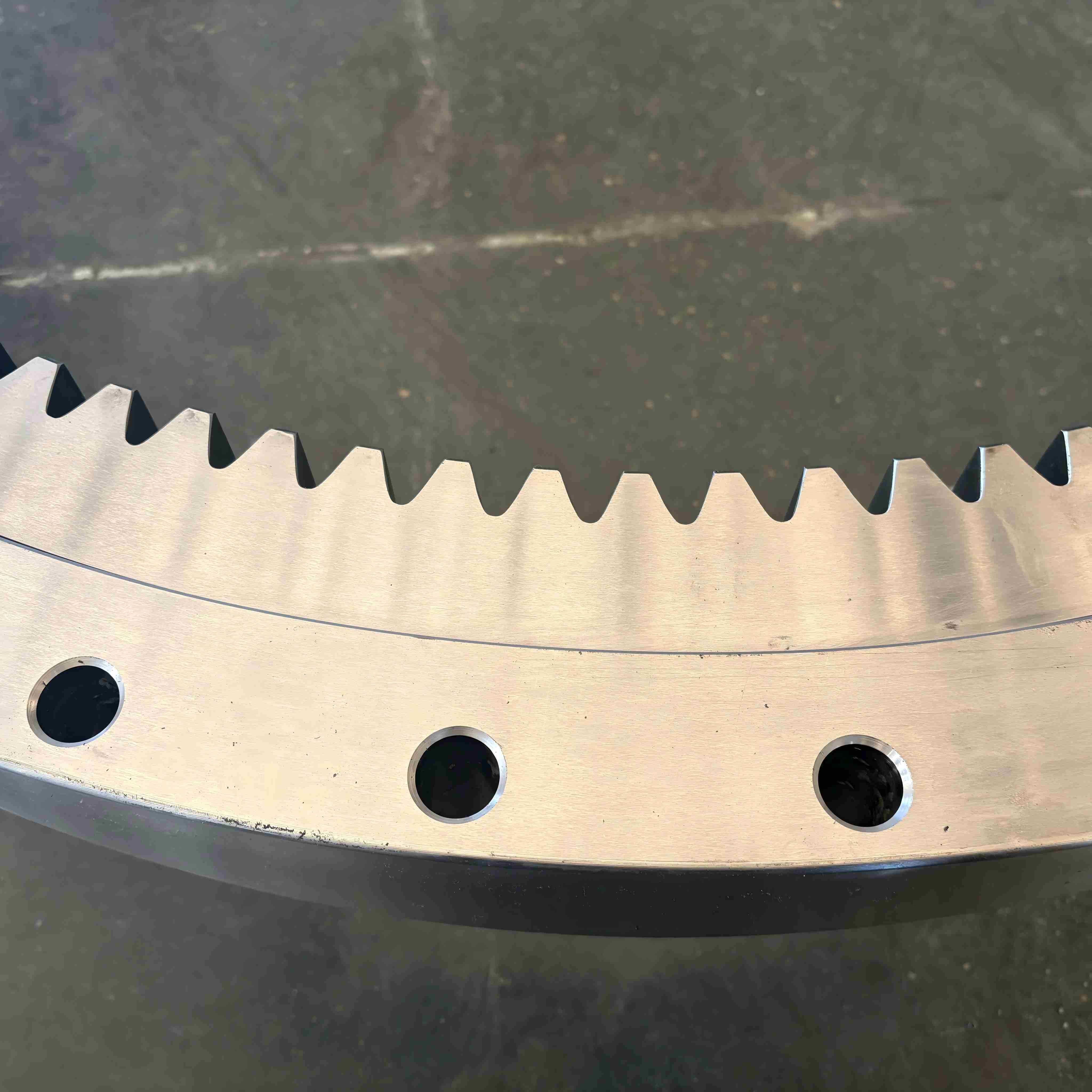
In one case, a client installing a large segmented gear ring experienced binding after installation. By following our fault diagnosis guidance, they were able to identify a flatness issue on one of the support segments. After re-machining the surface and following the correct bolting procedure, the ring rotated smoothly within its specified torque limits. This highlights the value of our full after-sales support, which includes bearing installation guidance and fault analysis to ensure long-term, stable operation.
Proper slewing bearing installation is a process of precision and diligence. By controlling the quality of the mounting surface and adhering to a strict bolting procedure, you can prevent distortion and ensure the bearing delivers its designed performance and lifespan.
If you are planning a critical installation or require technical support for our customized bearing solutions, contact our engineering team to ensure optimal performance from day one.