WhatsApp
 jessica.chai@ltzzc.com
 0086-379-69950051

Why Structural Stiffness Dictates High Load Slewing Bearing Life
As a slewing bearing engineer with a decade of experience, I frequently encounter a frustrating scenario for design teams. They specify a high-load slewing bearing with a load capacity that far exceeds the application's calculated forces, yet the bearing fails prematurely. The immediate assumption is a faulty bearing. However, the root cause is often hidden in plain sight: the support structure itself.
The nameplate capacity of a bearing is only valid when it is mounted to a sufficiently rigid structure. If the mounting surface flexes, twists, or deforms under load, the forces are no longer distributed evenly across the bearing's raceway. This creates intense pressure points that can destroy a bearing, regardless of its theoretical strength. Understanding this interaction between the bearing and its foundation is the key to achieving long, predictable service life in heavy machinery.
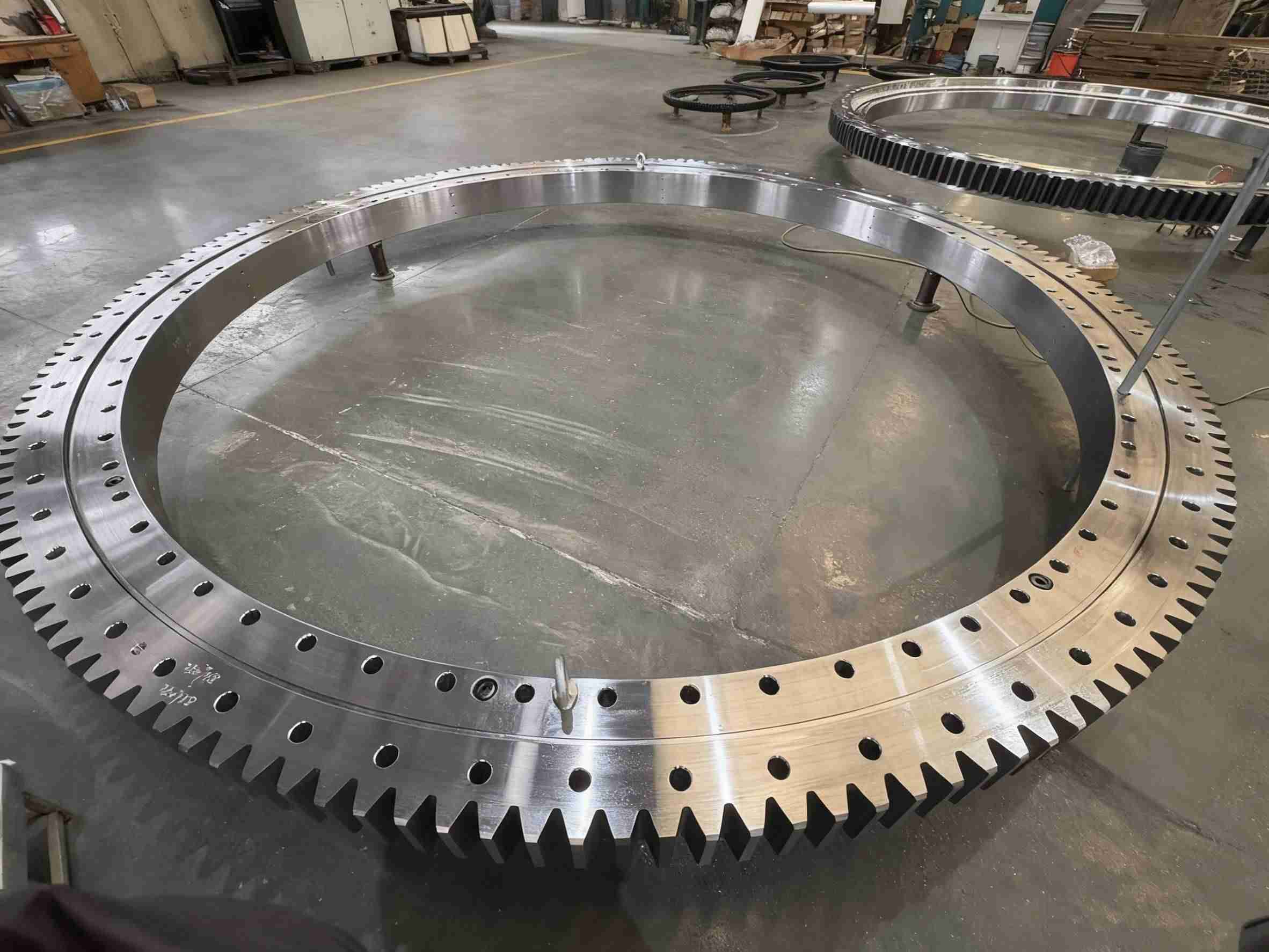
When Stiffness, Not Load, Is the Limiting Factor
Engineers are trained to focus on load ratings. But for large-diameter bearings, there is a critical boundary where the deflection of the support structure—not the bearing's inherent load capacity—becomes the primary factor determining its operational life. A high-load slewing bearing is designed to transfer massive axial, radial, and tilting moment loads, but it can only do so if the entire system is stiff enough to maintain the bearing’s precise geometry.
When the mounting flange or machine frame deforms, it distorts the bearing's circular shape into an oval. This seemingly small change has catastrophic effects on internal load distribution, concentrating immense force onto a few rolling elements. The bearing's published L10 life calculation becomes meaningless because the real-world operating conditions no longer match the ideal assumptions.
The table below illustrates the stark difference between operating on a rigid versus a non-rigid foundation.
| Characteristic | Scenario A: Rigid Support Structure | Scenario B: Flexible Support Structure |
|---|---|---|
| Load Distribution | Load is distributed evenly across a large arc of the raceway and multiple rolling elements. | The entire load concentrates on a few rolling elements at the points of maximum deflection. |
| Contact Pressure | Within design limits, leading to normal fatigue life (L10). | Exceeds material yield strength, causing plastic deformation (brinelling) and rapid failure. |
| Primary Life Limiter | Rolling contact fatigue, predictable by standard bearing life calculation. | Structural deflection, leading to unpredictable, premature failure from overload on small sections. |
| Failure Mode | Gradual spalling or pitting that develops over millions of cycles. | Rapid raceway indentation, cracked rolling elements, or cage failure. Can occur quickly. |
| System Performance | Smooth, consistent rotation with predictable torque and positioning accuracy. | Noisy operation, increased rotational torque, poor indexing accuracy, and potential for seizure. |
The boundary is crossed when structural deflection causes the clearance within the bearing to be completely consumed in one area, creating a "pinched" condition. At this point, the system's stiffness dictates performance, and adding a bearing with a higher load capacity will not solve the problem.
Common Design Flaws That Reduce System Rigidity
In my experience reviewing client designs, several common structural patterns consistently lead to stiffness problems. Identifying these early in the design phase is far less costly than dealing with field failures later. These flaws often seem like minor details but have a major impact on the performance of a precision slewing bearing.
Here are the most frequent mistakes to avoid when designing a bearing support structure:
-
Mistake 1: Under-specified Mounting Flange Thickness. A thin flange acts like a drumhead, flexing between mounting bolts. This is the most common cause of non-uniform load distribution.
Solution: The flange thickness should generally be no less than the height of the bearing ring it supports. Use Finite Element Analysis (FEA) to verify deflection under maximum tilting moment load. -
Mistake 2: Insufficient Radial Support. Relying solely on a flat mounting plate without vertical stiffeners or a cylindrical wall behind the bearing. The plate can easily "dish" or deform under load.
Solution: Integrate vertical ribs, gussets, or a full-height cylindrical support wall directly beneath the bearing seat. This dramatically increases the structure's section modulus and resistance to bending. -
Mistake 3: Large Distances Between Support Points. Mounting a large diameter bearing on a frame with widely spaced support members allows the structure to sag between those points.
Solution: Ensure the underlying machine frame provides continuous or near-continuous support. If using a grid or frame, decrease the spacing between support elements directly under the bearing path. -
Mistake 4: Ignoring Bolt Preload and Spacing. Incorrect bolt tension or excessive spacing allows microscopic separation between the bearing and the mounting surface, effectively reducing system stiffness.
Solution: Follow strict bolting procedures using calibrated torque wrenches. Ensure bolt spacing is adequate to provide uniform clamping pressure around the entire circumference.
Practical Methods for Assessing and Improving Structural Support
Moving from theory to practice requires a structured approach to designing and validating the rigidity of your machine frame. You cannot simply assume the structure is "stiff enough." You must verify it. Our quality management system, certified to ISO 9001:2015, emphasizes process control, and a similar mindset should be applied to your structural design.
Use this buyer's decision checklist during your design and prototyping phases to ensure your structure provides an adequate foundation.
Buyer's Decision Checklist for Structural Rigidity
- [ ] Perform FEA Simulation: Have you modeled the entire assembly (bearing, structure, and load) in an FEA program? The analysis must focus on the deflection at the bearing mounting surface, not just general stress levels in the frame.
- [ ] Check for Mounting Surface Flatness: Is your specified flatness for the mounting surface achievable and verified during manufacturing? A common rule of thumb is a flatness tolerance of 0.05 to 0.1mm for every 1000mm of raceway diameter.
- [ ] Analyze the Load Path: Have you traced the path of the tilting moment load from its point of application down through the bearing and into the foundation? Ensure there are no weak, flexible sections in this path.
- [ ] Evaluate Material Selection: Is the material of your support structure (e.g., A36 steel vs. high-strength steel) appropriate for the stiffness required? A higher modulus of elasticity will result in less deflection for the same geometry.
- [ ] Plan for Prototype Testing: Do you have a plan to measure actual deflection on a physical prototype? Using dial indicators or laser trackers at key points around the bearing under a simulated load can validate your FEA results.
- [ ] Review Bolting Strategy: Are you using the correct grade (e.g., 10.9 or 12.9) and quantity of bolts? The clamping force from the bolts is a direct contributor to the joint stiffness. Consult our bearing installation guide for best practices.
By systematically working through these points, you can shift your focus from simply meeting a load requirement to engineering a complete, high-performance rotational system. For complex applications like cranes, excavators, or wind turbines, this level of analysis is not optional; it is essential for safety and reliability.
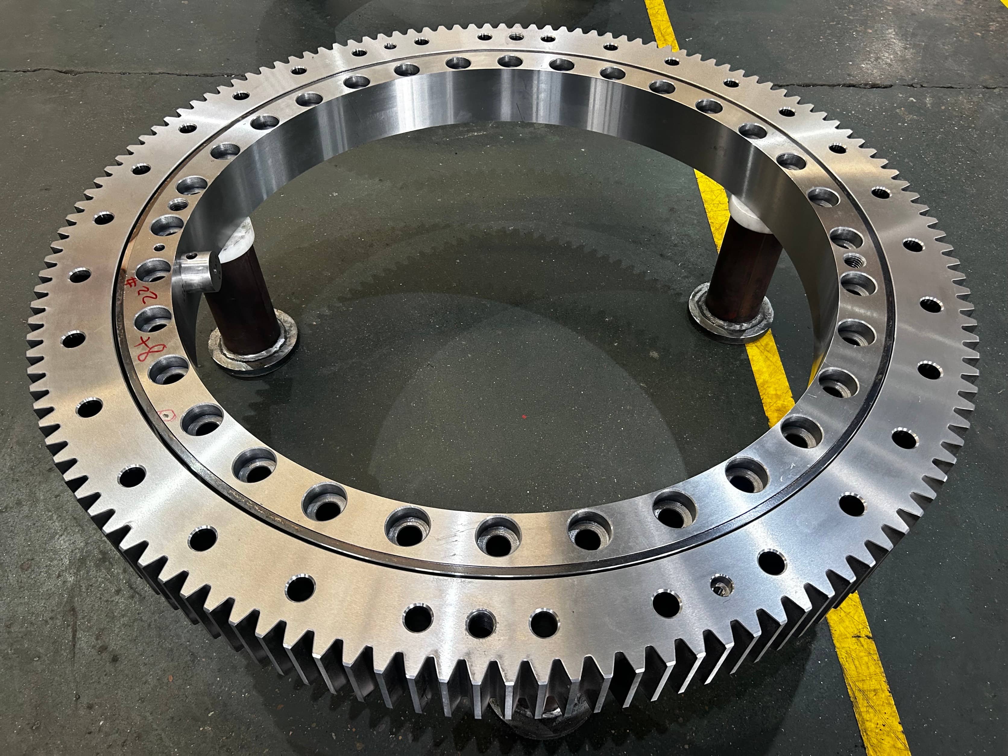
Specifying for System Performance, Not Just Bearing Capacity
When you select a bearing, you are not just buying a component; you are defining the heart of a dynamic system. A successful specification process looks beyond the catalog load ratings and considers the integrated performance of the bearing and structure.
At LTZC, we provide non-standard bearings and customized solutions precisely because standard off-the-shelf parts often don't account for unique structural interactions. When discussing your project with a supplier, the conversation should cover the entire system. Be prepared to share details about your support structure, expected deflection, and operational environment. This allows us to recommend a complete solution, not just a part number.
Our engineering process is backed by certifications from ISO, CCS, and ABS, ensuring every recommendation is based on verified standards and manufacturing excellence. Whether you require specific materials to match the thermal expansion of your structure or a unique internal clearance to accommodate known deflections, our advanced production capabilities can meet the need. With no MOQ and delivery in 30-90 days, we make it possible to source a truly optimized component without committing to mass production volumes.
Ultimately, the best high-load slewing bearing is one that is correctly integrated into a well-designed, rigid structure. By focusing on system stiffness first, you ensure that the bearing's full capacity can be utilized, leading to a more reliable, durable, and cost-effective machine.
If you are designing a system with a large-diameter bearing and have concerns about structural stiffness, submit your drawings to our engineering team. We can help you analyze your design and specify a bearing solution that ensures optimal performance and service life.