WhatsApp
 jessica.chai@ltzzc.com
 0086-379-69950051

How a High-load Slewing Bearing Is Rated for Tilt
How do you determine whether a bearing can safely carry an overturning load instead of only a vertical load? This is the question equipment engineers need answered before selecting a High-load slewing bearing for cranes, lifting platforms, excavators, rotating tables, offshore equipment, or other machinery with an offset load.
Tilt is usually expressed as a tilting moment. It occurs when the applied force acts away from the bearing centerline and tries to rotate one ring relative to the other. A bearing may appear suitable when the axial load is low, yet still be unsuitable because the moment load concentrates force onto a limited section of the raceway and mounting bolts.
Supplier capacity data must therefore be read as a system, not as a single load figure. The bearing raceway, rolling elements, gear teeth where applicable, mounting bolts, support structure, and load direction all affect the allowable condition. Early design work should compare the actual combined load case against the supplier’s approved load envelope.
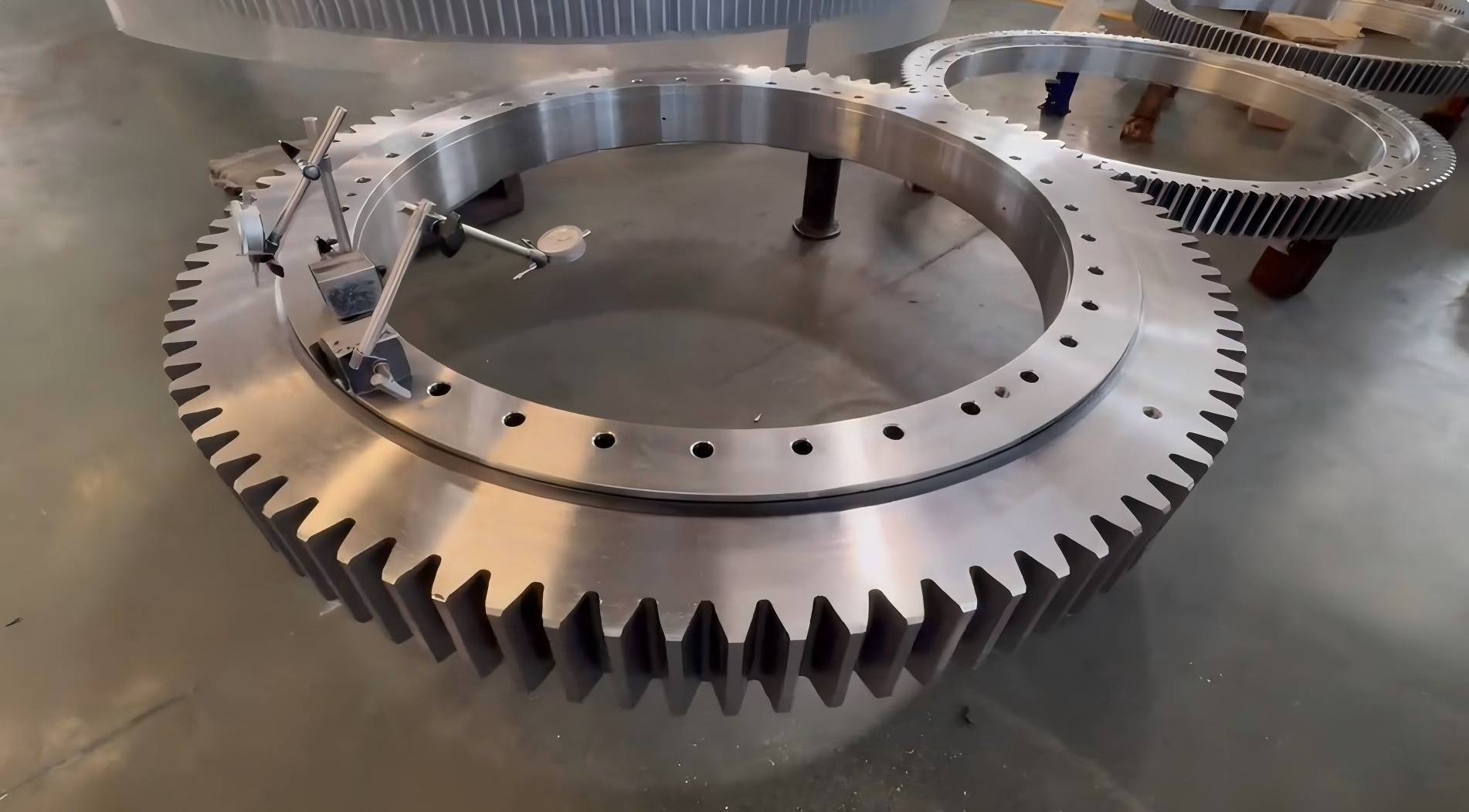
Translate machine loads into the bearing load case
The correct starting point is not the bearing catalog size. It is a free body diagram of the rotating structure. Engineers should identify every force that reaches the bearing and where each force acts relative to the bearing center.
A tilting moment is generated when a force has a lever arm. In simple terms, the moment increases when either the applied force or the distance from the bearing center increases. A boom, platform, bucket, tooling head, or suspended payload can all create this condition.
Load inputs to provide before rating the bearing
Axial load: The force acting perpendicular to the bearing mounting plane. This commonly comes from equipment weight, payload weight, or vertical process force.
Radial load: The force acting parallel to the mounting plane. Wind, acceleration, side pull, cutting force, and uneven terrain can add radial loading.
Tilting moment: The overturning effect around a horizontal axis. This normally governs when the load is far from the bearing center.
Drive torque: The torque required to rotate the structure. It is not the same as tilting moment, but it can affect gear selection and operating duty.
Load direction: The bearing may see the load from several directions during rotation, lifting, braking, or travel. The supplier needs the governing direction and whether it changes.
Operating condition: Include stationary holding, starting, stopping, vibration, shock, duty cycle, speed, temperature, and environmental exposure.
For early design, separate the load cases instead of presenting one blended “maximum load” value. For example, a machine may have a parked wind condition, a maximum payload condition, a travel condition, and an emergency stop condition. Each can place a different combination of axial load, radial load, and tilting moment on the ring.
The practical conclusion is straightforward: provide the supplier with the combined loads for each meaningful operating condition. This approach fits equipment with changing positions or intermittent shock. It does not replace a structural calculation of the surrounding frame, because a stiff bearing mounted on a flexible frame may experience uneven load transfer that the initial free body diagram does not show.
For selection references, see LTZC’s bearing selection guide before issuing an RFQ. A clear load schedule reduces the risk of comparing catalog values that were calculated under different assumptions.
Compare static load rating, tilting-moment rating, and bolt-joint limits to identify the governing capacity
There is no single capacity figure that answers every tilt question. Static load rating, tilting moment rating, and bolt joint limits address different possible failure modes. The governing figure is the one reached first under the actual combined load case.
| Capacity figure | What it evaluates in practice | What can happen if it is exceeded or misread | When it is most likely to govern | Selection limit |
|---|---|---|---|---|
| Static load rating | Raceway and rolling element contact under high stationary or slowly applied loading. | Local contact stress can cause permanent damage, rough rotation, reduced life, or degraded load distribution. | Heavy parked loads, supported booms, slow lifting equipment, and applications with long holding periods. | It does not by itself confirm that the bearing can resist the applied tilting moment or that the bolts are adequate. |
| Tilting moment rating | The bearing’s ability to resist overturning load through the raceway contact pattern and ring stiffness assumptions. | Rolling elements can become heavily loaded over a short arc while opposite areas unload. Rotation may become uneven and raceway damage may follow. | Offset payloads, long booms, elevated platforms, side mounted tools, and wind loaded rotating structures. | The listed value is valid only for the stated accompanying axial and radial loads, support conditions, and manufacturer method. |
| Bolt joint limits | The mounting connection between bearing rings and machine structure, including bolt tension, preload retention, flange stiffness, and hole layout. | Joint separation, bolt fatigue, loosening, ring distortion, fretting, and a rapid loss of raceway load sharing may occur. | High overturning moment, thin mounting flanges, discontinuous supports, vibration, shock, and repeated reversing loads. | A suitable bearing raceway cannot compensate for an inadequate bolt pattern or flexible mounting structure. |
A High-load slewing bearing can therefore be limited by the bolts even when the raceway capacity appears acceptable. This is common where designers increase the ring diameter to improve moment resistance but retain a mounting flange that is too flexible or use an unsuitable bolt arrangement.
Use the supplier’s load chart as a combined-load boundary. If the chart presents allowable axial load against tilting moment, locate the actual operating point using both values. If radial loading is present, confirm whether the chart includes radial load or whether a separate verification is required. Do not assume that maximum published axial load and maximum published moment can be applied simultaneously.
The conclusion for equipment engineers is to select against the lowest allowable margin among raceway contact, tilting moment, bolt joint, gear capacity, and supporting structure. This applies to all moment loaded slewing systems. It does not mean every project requires the largest ring; improving load position, flange stiffness, or bolt layout may change the governing limit.
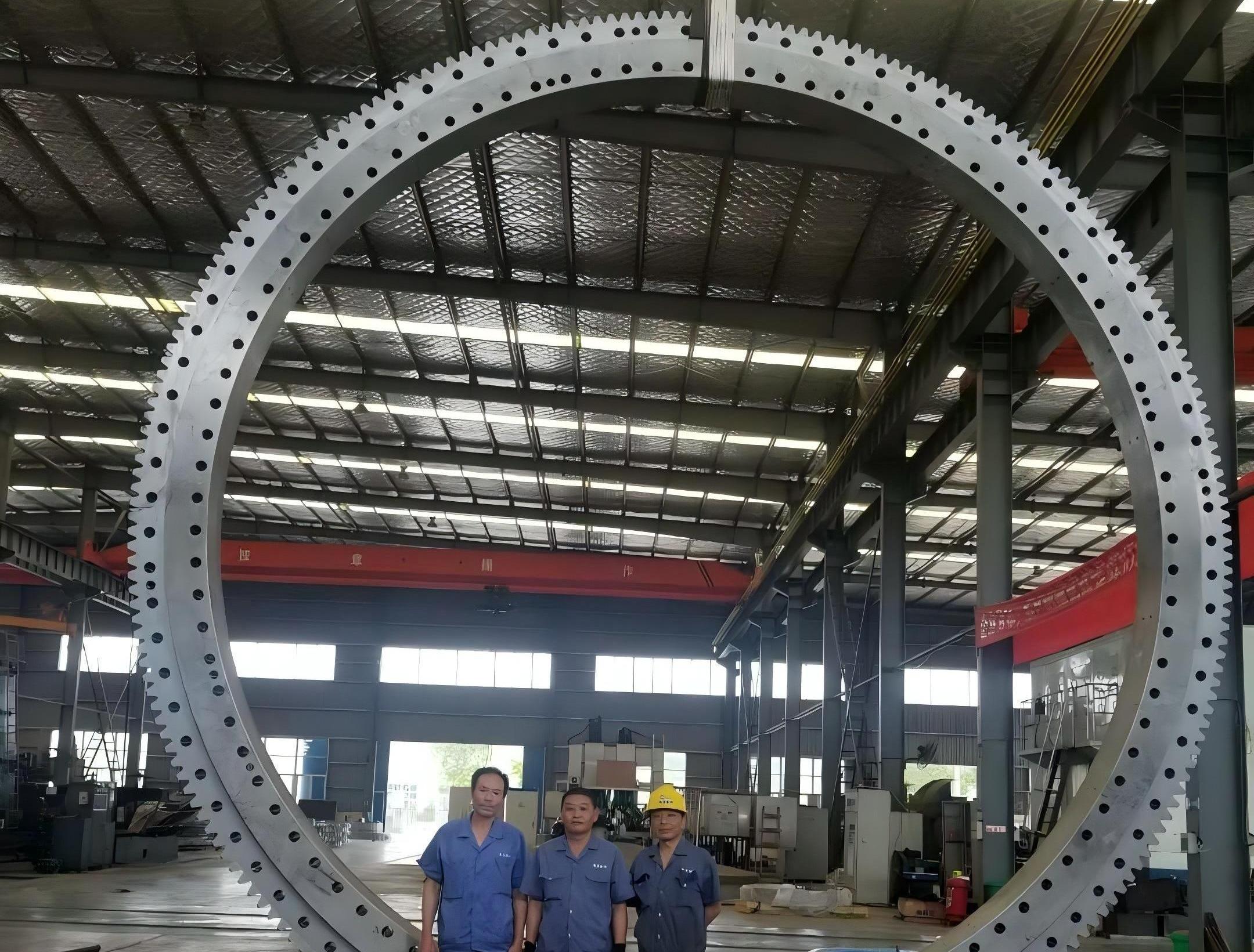
Read a bearing load chart without combining incompatible values
A bearing load chart is often the fastest way to screen a proposed design. It is also easy to misuse. Charts may show axial force on one axis and tilting moment on the other, with curves representing different radial load conditions. Other suppliers may publish a table of permitted combinations instead.
Before using any chart, verify the following items with the bearing manufacturer:
Whether the values are for static capacity, operating capacity, or a defined service condition.
Whether the stated tilting moment applies with an axial load, radial load, or both.
Whether the values assume a full circular mounting surface with adequate stiffness.
Whether bolt preload and bolt grade are part of the stated limit.
Whether the load is stationary, slowly rotating, continuously rotating, reversing, or subject to shock.
Whether the gear ring must be checked separately for transmitted drive torque.
Consider an elevated work platform with a turntable bearing. When the platform is centered, the axial load may be the dominant input. When the platform is extended, the same weight produces a much larger moment because the center of gravity moves outward. If the platform is exposed to side force or braking, radial load is added at the same time.
In that example, selecting from axial load alone would be incorrect. Selecting from moment alone may also be incorrect if the supplier’s rating assumes a different axial load. The correct action is to calculate each platform position, identify the highest combined demand, and submit the resulting cases for supplier review. This method fits early feasibility work and detailed engineering. It does not replace machine stability analysis, which must consider the entire equipment base and support condition.
Where the ring includes external or internal teeth, the bearing and gear must be considered as connected but separate checks. A larger bearing may carry the moment while the gear teeth still require verification against the drive torque and duty. LTZC can also support related slewing ring gear requirements when the rotating connection includes a geared ring.
Check the mounting structure before finalizing the ring size
The bearing does not sit on an abstract flat surface. It transfers concentrated forces into two machine flanges. If either flange bends, the bearing rings can distort and the rolling elements may no longer share load as intended.
For tilt loaded equipment, the loaded side of the ring tends to press into the support while the opposite side may tend toward separation. The mounting bolts and flange stiffness must resist this tendency together. A ring selected from a load chart can still perform poorly if the surrounding structure is too thin, interrupted by large openings, unevenly machined, or unsupported near the bolt circle.
Mounting design checks for a tilt loaded application
Confirm that both mounting faces are flat, clean, and fully supported around the intended bolt locations.
Review the support flange for local bending near the highest loaded sector, not only for average stress around the full circumference.
Specify bolts, tightening method, and preload according to the bearing supplier’s installation instructions.
Check whether the load reverses direction. Reversing moment can be more demanding for joint retention than a constant load direction.
Assess the effects of welded fabrication distortion, paint thickness, burrs, and local weld features on the mounting faces.
Plan access for tightening, inspection, lubrication, and replacement before the machine frame is released for fabrication.
A good rule is to treat the bearing ring and mounting structure as one load path. This recommendation is especially relevant for fabricated bases, mobile machines, and structures with cutouts near the bolt circle. It is less restrictive for a heavily machined, fully supported mounting interface, but even then the supplier’s mounting requirements still apply.
Detailed assembly practice also matters. Review LTZC guidance on bearing installation when preparing the flange, bolt procedure, and inspection plan.
Avoid selection errors that hide tilt risk
The following mistakes repeatedly create a mismatch between catalog capacity and installed performance. Each can be addressed before manufacturing begins.
| Common mistake | Why it creates risk | Immediate corrective action |
|---|---|---|
| Using payload weight only | It ignores the lever arm, dynamic effects, structure weight, tooling, and side loads. | Prepare a load schedule that includes force location and operating position for every governing case. |
| Adding separate maximum values | Published axial, radial, and moment maxima may not be allowed at the same time. | Request a combined load verification based on the supplier’s approved rating method. |
| Ignoring bolt joint capacity | The ring may be adequate while bolt tension or flange separation governs first. | Submit the bolt pattern, flange thickness, support arrangement, and joint details with the load data. |
| Assuming a rigid support frame | Flexible flanges distort the ring and create uneven rolling element loading. | Review local support stiffness and avoid unsupported sectors around the mounting circle. |
| Checking only normal operation | Parking, wind, braking, impact, transport, and emergency conditions can generate the highest moment. | List abnormal but credible load cases separately and identify which case governs each component. |
LTZC Bearings Co.,Ltd. provides customized bearing solutions based on working conditions, existing designs, and technical specifications. This is useful when a standard catalog ring does not match the required mounting interface, material choice, size, or performance need. There is no MOQ, which can help during prototype and low volume equipment development. Quoted delivery planning is typically within the stated 30 to 90 day range, subject to the confirmed design and order requirements.
For quality system review, LTZC holds ISO9001:2015, ISO14001:2015, and ISO45001:2018 certifications, with ISO, CCS, and ABS certification stated in its company credentials. These credentials support supplier assessment, but they do not remove the need to validate the actual load case, mounting design, and application duty for each bearing selection.
Prepare an RFQ that allows a meaningful tilt rating review
A supplier cannot responsibly confirm a tilt rating from bearing diameter and equipment weight alone. The most useful RFQ package gives enough information to assess the actual connection and load combination.
General arrangement drawing showing the bearing location, load directions, and center of gravity positions.
Axial load, radial load, tilting moment, and drive torque for each operating case.
Distance from each applied load to the bearing centerline.
Rotation range, speed, duty cycle, reversing frequency, and expected service environment.
Mounting drawings showing flange geometry, bolt arrangement, support zones, and available installation space.
Required gear form, gear position, drive arrangement, lubrication approach, and sealing expectations where applicable.
Existing bearing drawing or part number if the project is a replacement or redesign.
If the application requires a nonstandard envelope or interface, LTZC can review drawings for non-standard bearings and propose a configuration suited to the stated working conditions. For equipment using a drive unit rather than a separate motor and pinion arrangement, the related Slewing Drives range may also be relevant.
Submit your drawings and combined load cases to request selection advice for a tilt loaded slewing bearing.