WhatsApp
 jessica.chai@ltzzc.com
 0086-379-69950051

How to Calculate Loads for a Single Row Ball Slewing Ring
What load numbers does a supplier actually need before it can confirm a bearing size? Most inquiries we see carry a single figure, such as "50 kN capacity", and nothing else. That is not enough. A Single Row Ball Slewing Ring carries axial force, radial force and overturning moment at the same time, and the combination decides whether a given diameter survives or fails. This guide shows how to calculate each component, combine them into load cases, and present them so a supplier can check your selection quickly.
I have spent ten years in slewing bearing sales and after-sales support. The most common cause of an oversized quote, or a bearing that fails early, is incomplete load data at the specification stage.
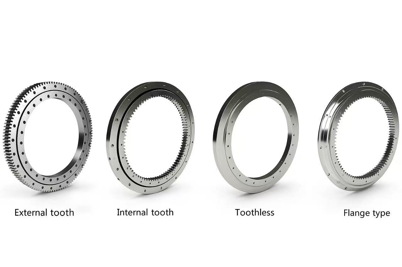
What Load Data a Supplier Needs Before Sizing
Start with the three primary loads and the context around them. Each item below changes the bearing selected.
| Data item | Unit | Why it matters | Typical omission |
|---|---|---|---|
| Axial force (Fa) | kN | Acts along the rotation axis; sets ball contact stress | Self weight of the rotating structure left out |
| Radial force (Fr) | kN | Acts across the axis; wind, braking, side pull | Treated as zero because it looks small |
| Overturning moment (M) | kN·m | Usually the dominant load on the raceway | Taken at the wrong reference plane |
| Load type | Static / working | Defines which rating curve applies | Only peak loads given, no duty cycle |
| Rotation speed and duty | rpm, hours/day | Separates slow positioning from continuous slewing | "Continuous" written with no figures |
| Mounting space | mm | Limits outer diameter, height and bolt circle | Dimensions given without the structure drawing |
Give the reference plane for the moment explicitly. A moment measured at the boom pivot is not the same as one measured at the bearing's mounting face. The shift can change the number noticeably when radial force acts above the bearing.
Method for Converting Axial Force, Radial Force and Overturning Moment into Supplier-Ready Load Cases
This is the part most inquiries skip. Follow these steps in order. Each has a checkpoint and a typical failure reason.
Define the coordinate system. Mark the rotation axis and the bearing mounting plane on a sketch. Fix the sign convention: axial downward positive, moment tipping toward the load positive.
Checkpoint: every load on the sketch has an arrow and a distance from the axis.
Typical failure: moments calculated about the structure's center of gravity instead of the bearing plane.
List every load source separately. Include payload, equipment self weight, counterweight, wind, inertia from starting and stopping, and any process force such as digging or drilling.
Checkpoint: each source has its own magnitude, position and direction.
Typical failure: lumping "dynamic effects" into one multiplier with no basis.
Sum the axial force. Add all vertical forces acting through the bearing, with counterweights and self weight included.
Checkpoint: the total matches the weight the foundation actually supports.
Typical failure: forgetting that an upward pull, such as a tie-down or uplift, reduces or reverses axial load.
Sum the radial force. Combine horizontal forces in the worst direction.
Checkpoint: wind, braking and side pull are added as vectors, not as simple numbers.
Typical failure: ignoring radial force because the moment dominates. Radial force also creates extra moment when it acts above the bearing plane.
Calculate the overturning moment. Multiply each force by its lever arm to the bearing center and add them with signs. Add the moment from radial forces: force times height above the mounting plane.
Checkpoint: the result is reasonable when you check it against the largest single force times its arm.
Typical failure: counterweight moment subtracted in the loaded case but also applied in the unloaded case, where it can become the worst case.
Build separate load cases. Typical cases are working load, maximum working load, out of service (storm), and test or assembly load. Record Fa, Fr and M together for each case.
Checkpoint: the three values in a row come from the same instant. Do not mix the maximum moment from one case with the maximum axial force from another unless it can really occur.
Typical failure: submitting only one envelope case, which leads to oversizing or an undersized selection.
Attach duty data and format the table. Add rotation speed, hours of operation and an estimate of how often each case occurs.
Checkpoint: the supplier can match each row to a static check and a service life check.
Typical failure: giving a safety factor you already applied without saying so, which leads to double counting.
State clearly whether the numbers are characteristic (unfactored) loads or already include a safety factor. The supplier applies its own equivalent load method and its own factors against its rating curves, so unlabeled factored loads cause confusion.
Worked Example With Illustrative Numbers
The numbers below are a hypothetical example to show the arithmetic. They are not a customer case. Assume a small rotating platform with a boom:
Lifted load: 20 kN at 4.0 m from the axis
Boom and equipment weight: 15 kN at 2.5 m
Counterweight: 30 kN on the opposite side at 1.5 m
Wind force: 5 kN horizontal, acting 3.0 m above the bearing plane
| Load case | Fa (kN) | Fr (kN) | M (kN·m) | Note |
|---|---|---|---|---|
| A. Working, with lifted load | 65 | 5 | 72.5 + 15 = 87.5 | Wind moment (5 × 3.0 = 15) assumed to act in the same direction |
| B. No lifted load | 45 | 5 | 37.5 − 45 = −7.5, plus wind 15 | Check the direction, because the counterweight now dominates |
Case A: Fa = 20 + 15 + 30 = 65 kN. Moment from loads = 20 × 4.0 + 15 × 2.5 − 30 × 1.5 = 72.5 kN·m. Adding the wind moment gives 87.5 kN·m. Case B shows why a second case matters: without the lifted load the counterweight can tip the structure the other way, and the ball path loads a different zone of the raceway.
Send both rows. A supplier checking only Case A would never see the reversed moment.
Common Mistakes That Lead to Wrong Selections
Quoting capacity instead of loads. Catalog ratings describe the bearing, not your application. Supply your own Fa, Fr and M.
Using the axial load alone. In many machines the moment sets the size. A bearing that suits the axial force can still be far too small for the tilting moment.
Skipping static and out of service cases. A storm or transport condition can exceed the normal working load. This applies mainly to outdoor equipment; for an indoor positioning table it may be a minor check.
Ignoring structure stiffness. The bearing needs a rigid, flat mounting surface. A calculation cannot compensate for a flexible frame that distorts the raceway.
Not saying whether a gear is needed. Tooth force adds load and affects the bearing choice. If the application needs a slewing ring gear, give the drive torque and pinion data with the inquiry.
A single-row ball design suits many medium-load applications with combined loads and limited installation height. If your moment is very high relative to the available diameter, or the application needs unusual stiffness, other raceway layouts may fit better. Ask the supplier to compare options instead of assuming one design fits.
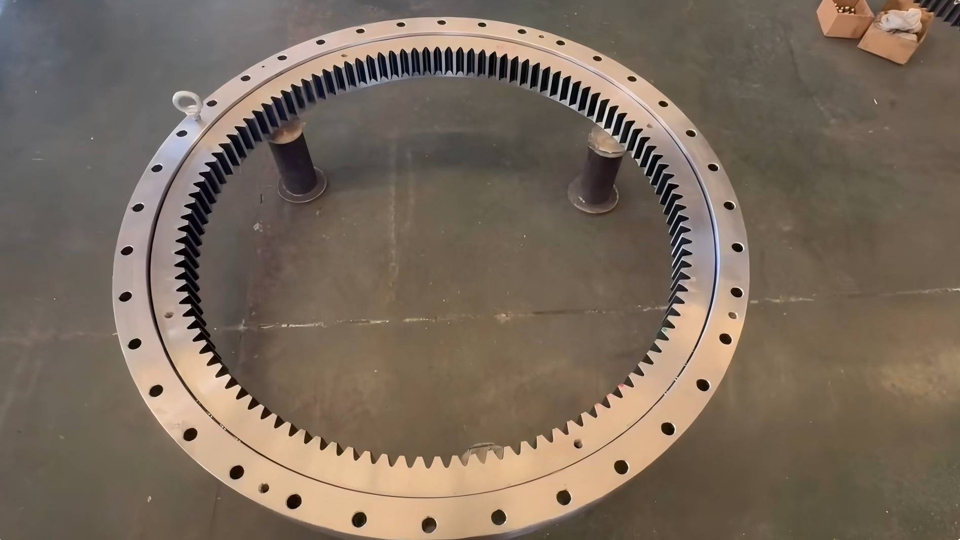
Checklist Before You Send the Inquiry
Run through this list. If you cannot answer an item, say so in the inquiry; a supplier can often help estimate it.
Sketch with axis, mounting plane and load positions.
Load case table with Fa, Fr and M in the same row.
Statement of whether loads include safety factors.
Rotation speed, working hours and the share of time in each case.
Maximum outer diameter, height and bolt pattern limits.
Operating temperature, environment and any special material or sealing needs.
Drive type: pinion on a gear ring, or a Slewing Drives unit that combines bearing and drive.
Planned mounting and tightening method, so that bearing installation requirements can be matched to the design.
For a first look at design families before you build your load table, the bearing selection guide gives a useful framework. If your envelope is tight, a thin section bearing may be worth comparing. When your drawing does not match a standard size, non-standard bearings may be the better path.
What to Expect From the Supplier
With a clean load case table, a supplier can check static capacity and service life against its rating data and propose a precision slewing bearing with matching size, material and gear options. LTZC works under ISO9001:2015, ISO14001:2015 and ISO45001:2018 management systems, with certification by ISO, CCS and ABS. We build customized solutions around your working conditions, existing designs and technical specifications, with no MOQ and a delivery time of 30 to 90 days depending on the design. Complete load data at the start is what keeps that schedule realistic, because it avoids rework during drawing confirmation.
If you have a load case table or a preliminary drawing, send it to our engineering team for selection advice on your Single Row Ball Slewing Ring, and we will review the data and tell you what is missing.