WhatsApp
 jessica.chai@ltzzc.com
 0086-379-69950051

When Does a Single Row Ball Slewing Ring Fit?
How can a design engineer tell whether one row of balls will carry an equipment load safely, or whether the concept needs a different bearing arrangement? The answer depends less on the equipment name and more on the real force path: axial force, radial force, overturning moment, shock exposure, support structure stiffness, and duty cycle.
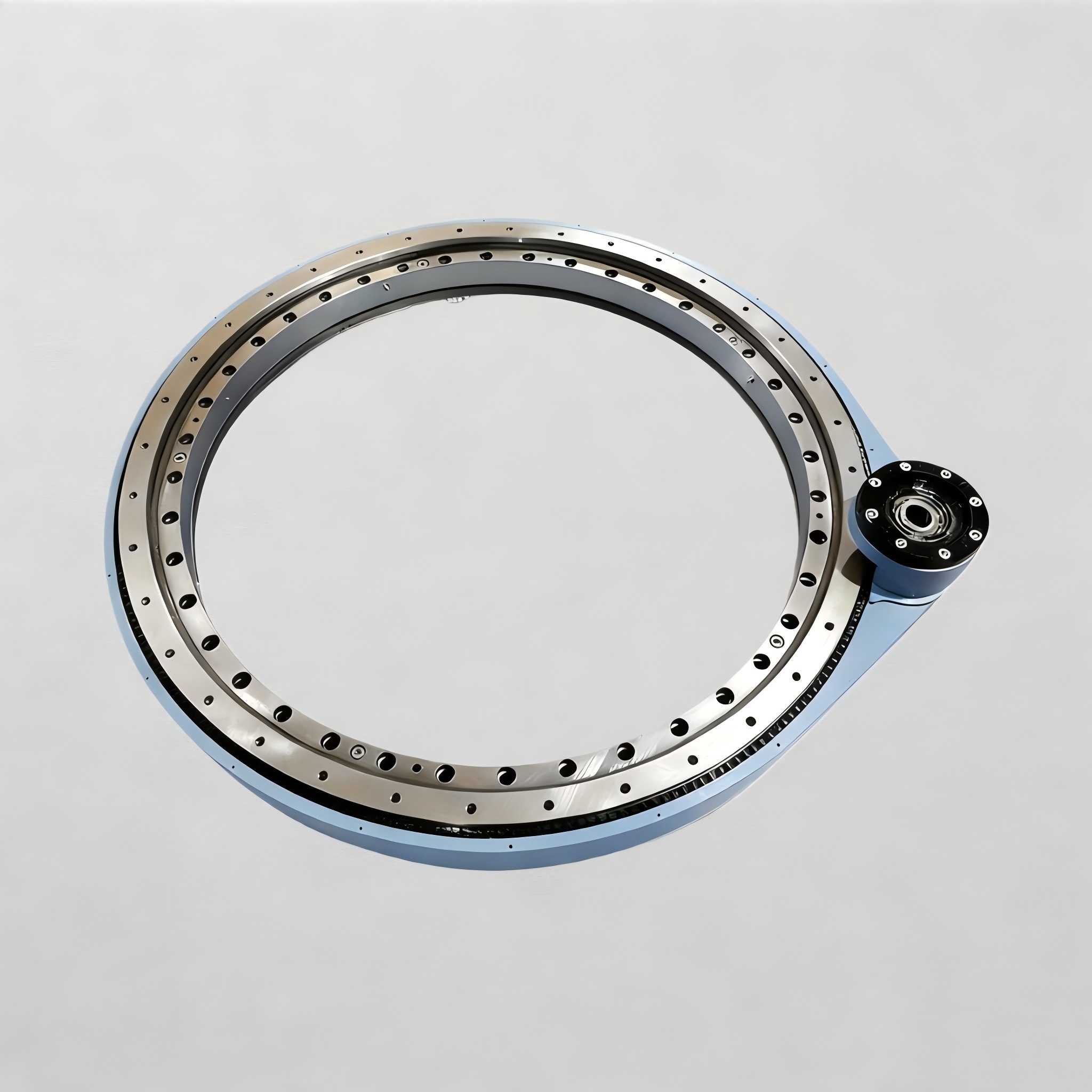
A Single Row Ball Slewing Ring is often considered early because it can support combined loading while keeping the bearing arrangement relatively simple. That can be a sound direction for turntables, light handling equipment, positioning assemblies, and other machines with controlled motion. It is not automatically the right answer for every rotating structure. A poor match can lead to uneven contact, mounting distortion, unstable rotation, or early raceway damage.
For early equipment design, start by identifying what the bearing must resist rather than starting with an outside diameter or a familiar prior design. The following checks help establish whether a single row ball arrangement fits the load profile, and where its operating boundary lies.
Start with the actual load path instead of the machine category
The first decision is not “Does this machine rotate?” It is “What forces reach the bearing, from which direction, and under what operating condition?” A bearing that works well beneath a level, centrally loaded platform may not suit the same platform when a tool, payload, or drive unit sits far from the rotation center.
For a ball based slewing arrangement, the rolling elements transfer load between the inner and outer rings through the bearing raceway. The force distribution changes when the applied load changes direction or moves off center. This is why a concept review should separate axial force, radial force, and moment rather than treating them as one general load value.
| Load condition | What it affects in practice | When a single row ball concept may fit | When further review is needed |
|---|---|---|---|
| Axial loading | Pushes the rings together or apart and determines how the balls contact the raceways. | Useful when vertical loading is controlled and the supporting frame shares the load evenly around the ring. | Review the arrangement if the load direction can reverse, fluctuate sharply, or concentrate near one mounting area. |
| Radial loading | Acts sideways on the ring and can shift contact toward one side of the raceway. | Can be appropriate where side force is moderate and guided machine members limit lateral movement. | Consider another concept where side loading is a primary operating force rather than an occasional condition. |
| Overturning moment | Tilts one ring relative to the other, increasing load on part of the bearing circumference. | Fits compact structures with a short load offset and a stiff, well supported mounting zone. | Needs deeper analysis when a boom, arm, elevated payload, or offset actuator creates sustained tilting force. |
| Shock loading | Creates brief force peaks that can interrupt smooth rolling contact and stress the support structure. | May fit controlled indexing or slow positioning with limited impact. | Choose another arrangement or obtain detailed engineering review for impact, sudden stops, dropped loads, or repeated collision risk. |
Conclusion: use this arrangement when no single load component dominates the design and the frame keeps the rings aligned. The reasoning is straightforward: ball contact can accommodate combined forces, but the load must remain distributed instead of being driven repeatedly into a small arc of the raceway. This fits controlled rotating equipment. It does not fit a concept that relies on the bearing to compensate for a flexible chassis or poorly controlled external loads.
During concept development, draw free body diagrams for both the normal operating position and the unfavorable position. Include the payload center of gravity, drive forces, external tool forces, braking reaction, and any transport or maintenance position that changes the load direction. A design that appears balanced in one orientation can become moment dominated in another.
Boundary analysis for moderate combined loads and demanding applications
Single row ball designs suit moderate combined loads when the equipment has controlled rotation, reasonably even mounting support, and limited shock. Their practical boundary is reached when stiffness, repeated impact, or overturning moment becomes the governing requirement rather than simple rotational support.
The table below compares the design boundary in terms an engineer can apply during preliminary selection. It is not a substitute for load calculation or drawing review, but it identifies which concept deserves the next level of analysis.
| Design condition | Single row ball design response | Suitable application direction | Where another bearing type may be better |
|---|---|---|---|
| Moderate combined axial and radial loads | Can carry both directions of loading when ring support and load distribution remain stable. | Rotary tables, controlled positioners, and compact rotating assemblies with restrained side force. | Move beyond this concept when the radial component becomes the main duty load or varies unpredictably. |
| Limited overturning moment | Can resist tilting force, provided the mounting structure keeps both rings supported around the circumference. | Short offset loads and compact tooling located near the rotation axis. | Consider a bearing arrangement intended for higher moment stiffness when long arms, raised loads, or large offsets govern the design. |
| Low shock duty | Works best when acceleration, deceleration, and contact events are controlled. | Positioning operations and smooth intermittent rotation. | Review roller based or other purpose selected arrangements when repeated impacts, abrupt reversal, or frequent hard stops are present. |
| High structural stiffness | Maintains more consistent raceway contact because ring distortion is reduced. | Machined support faces with continuous backing and well planned bolt locations. | Do not expect the bearing to correct a thin, warped, segmented, or unsupported mounting frame. |
| High positioning stiffness demand | May provide acceptable rotation support, but deflection under moment can become the limiting concern. | General rotation where small elastic movement does not affect the process. | Use a higher stiffness concept when tool position, sensor alignment, or process accuracy is sensitive to deflection. |
The practical mistake is to evaluate only the total force. Two designs can have a similar total load but behave very differently. A centered vertical payload primarily creates axial loading. Move that same payload outward and the overturning moment rises, concentrating contact on one portion of the ring. If the mounting structure also bends, the bearing sees a less favorable load distribution than the original calculation assumed.
Conclusion: select a single row ball design when the combined load capacity requirement is moderate and the structure controls ring alignment. Choose a different bearing type when shock resistance, high moment stiffness, or persistent side loading is the main design driver. The limit is not merely bearing size; it is the interaction between load, frame stiffness, motion control, and mounting quality.
Check whether the structure protects or distorts the bearing
A slewing bearing is part of an assembly, not an isolated purchased component. The inner and outer rings depend on their mating structures to preserve geometry. Even an appropriately selected ring can perform poorly if one mounting face is uneven, if support is discontinuous, or if bolts are tightened against a distorted frame.
Review mounting surface flatness early, before finalizing the weldment, casting, or machined platform. The relevant question is whether both bearing rings receive continuous, stable support in all operating positions. Local gaps and flexible regions can make a portion of the ring carry more load than intended.
Use this concept review procedure
Map the support faces. Identify where the inner ring and outer ring are backed by structure. Look for openings, thin bridge sections, access cutouts, and unsupported areas near high load zones.
Locate the load offset. Measure the conceptual distance between the rotation axis and each payload, actuator, tool, or drive load. Offset creates moment, even when the vertical payload itself appears manageable.
Review load reversals. Determine whether the machine can pull upward, push downward, reverse direction, or transition between loaded and unloaded states. A one direction assumption can be unsafe if service conditions change.
Identify shock sources. Include end stops, braking events, material impact, transport vibration, manual handling, and emergency stops. If these dominate the duty, a smooth operation assumption is not valid.
Match the gear arrangement. Confirm that the drive applies force without introducing avoidable side loading or local structural distortion at the geared ring.
Submit the concept for review. Share the load cases, interface drawing, mounting concept, and intended motion with the bearing supplier before freezing the structure.
This procedure fits early stage design because it exposes structural conflicts before a detailed bearing drawing is released. It does not replace final engineering verification. Final selection still requires the full operating data, mounting details, and arrangement of the drive system.
When the rotation is powered, the gear ring interface deserves equal attention. Gear mesh forces do not act as an abstract torque value; they introduce directional loading into the ring and surrounding structure. A drive mounted on a flexible bracket can change mesh conditions and contribute to uneven load transfer. For geared rotation concepts, review the available slewing ring gear options alongside the bearing arrangement rather than treating them as separate purchases.
Compare bearing concepts before locking the layout
A single row ball arrangement is one option among several bearing concepts. The correct comparison is based on the dominant operating requirement, not a simple preference for balls or rollers. The list below helps narrow the direction without making unsupported performance promises.
Choose a single row ball arrangement when the machine needs combined loading support, controlled rotation, moderate moment demand, and a compact ring based layout. It is a practical fit for equipment where the frame is stiff and impacts are limited.
Consider a higher stiffness arrangement when angular deflection affects tool accuracy, sensor alignment, or process repeatability. In these cases, the issue may be structural stiffness as much as bearing rolling capacity.
Consider a design intended for harsher shock duty when repeated impacts, abrupt starts, or sudden stops are normal operating events. A ball based concept should not be selected simply because nominal loads appear acceptable.
Consider a separate radial guidance strategy when lateral force is continuous or when another machine component can carry side loading more effectively. This can prevent the slewing ring from becoming the sole answer to every force direction.
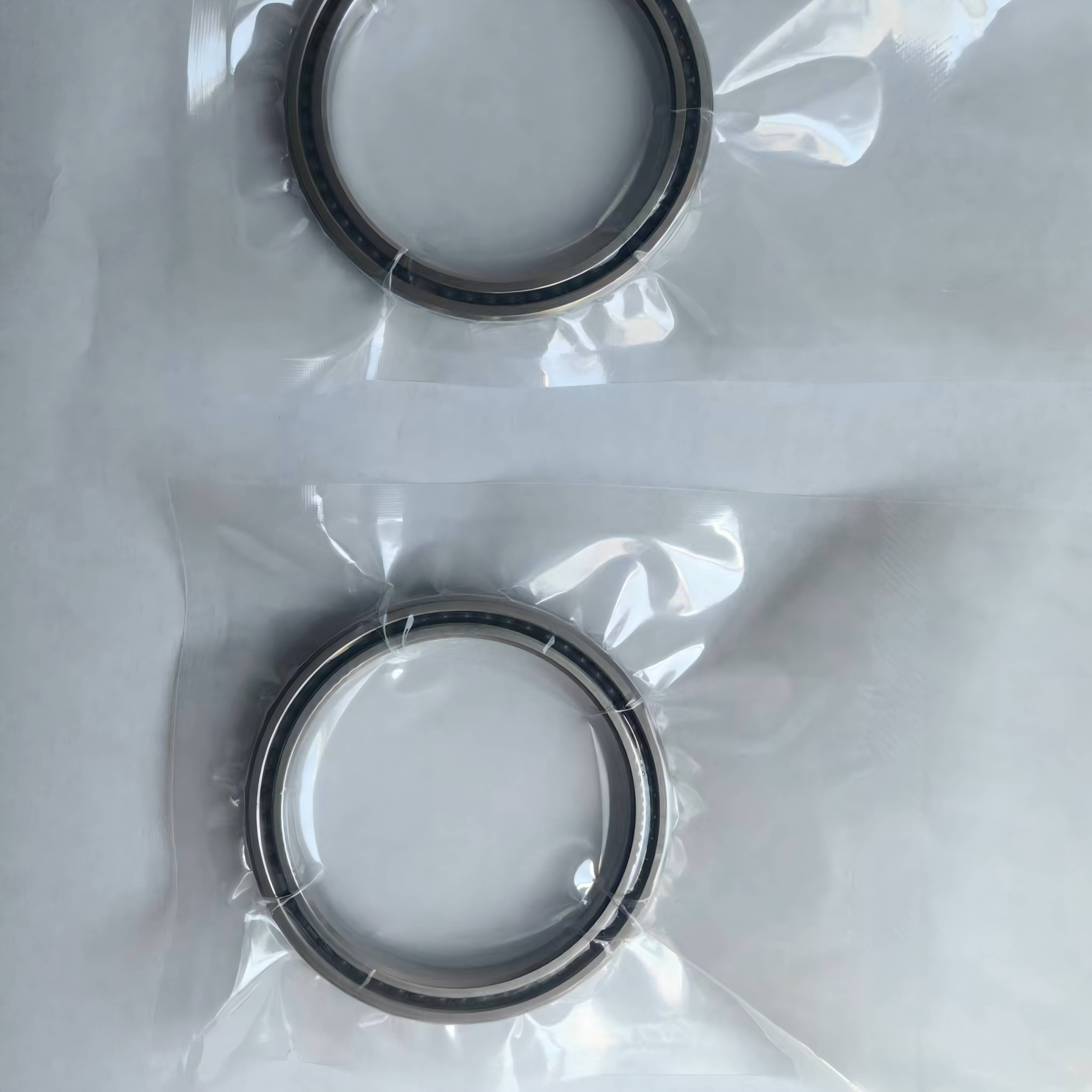
Consider a thin section bearing when the design need is compact rotary support in a different geometry rather than a large ring that carries major overturning force. Review LTZC’s thin section bearing range when the application geometry points in that direction.
A slewing drive system also changes the design discussion. A self contained drive may simplify rotational actuation, but it does not remove the need to verify moment, side force, and mounting support at the bearing interface. Engineers comparing powered arrangements can review LTZC Slewing Drives with the same load path in mind.
Conclusion: compare concepts by their limiting condition. If controlled combined loads define the design, a single row ball option may fit. If stiffness, shock, or sustained moment defines the design, begin with an alternative concept or ask for a technical assessment. The limit of a concept comparison is that no category label can replace actual load cases and mounting drawings.
Prevent selection mistakes that appear after prototype assembly
Many bearing issues begin with an early assumption that was never challenged. The following mistakes are especially relevant when narrowing a slewing bearing design.
Using only payload mass: Payload alone omits offset, acceleration, external process forces, and braking. Correct this by listing every force and its distance from the rotation axis.
Ignoring unfavorable orientations: A platform may be level during one task and tilted during another. Correct this by reviewing each permitted equipment position, including maintenance and transport conditions.
Assuming the frame is rigid: A ring can be selected against calculated load and still suffer from distorted support. Correct this by reviewing support continuity and planned machining before final release.
Separating bearing and drive decisions: A pinion force or actuator arrangement can add radial loading and local deformation. Correct this by reviewing the bearing, gear, drive bracket, and support frame together.
Leaving installation until the end: Incorrect mounting practice can undermine a suitable selection. Plan access, tightening sequence, lubrication access where applicable, and inspection space as part of the layout. LTZC provides guidance for bearing installation planning.
Copying a prior machine blindly: A previous ring may have operated under different loads, duty, geometry, or environmental exposure. Use prior designs as references, not proof of suitability.
For nonstandard equipment, the safest route is to provide the operating conditions and existing interface details for review. LTZC supplies customized bearing solutions based on working conditions, existing designs, and technical specifications, including requirements for particular materials, sizes, and performance needs. Where the standard concept does not suit the machine, review non-standard bearings before adapting the structure around an unsuitable catalog choice.
Prepare an RFQ that produces a usable engineering response
An RFQ should give the supplier enough information to evaluate the bearing concept, not just quote a ring diameter. The more clearly the application is described, the easier it is to identify whether the selected arrangement is within its intended boundary.
Include these items with the inquiry
Application description and equipment function.
Axial radial loads for normal, maximum, and reversed operating conditions.
Overturning moment sources and load offsets from the rotation center.
Rotation mode, including continuous rotation, intermittent indexing, reversing, or holding position.
Known shock events, emergency stops, and external process forces.
Inner and outer ring mounting dimensions, support details, and available space.
Preferred gear arrangement, drive concept, and required connection interface.
Existing drawing, previous bearing reference, or target assembly drawing.
LTZC Bearings Co.,Ltd. can support customized bearing solutions based on these working conditions and drawings. The company operates under ISO9001:2015, ISO14001:2015, and ISO45001:2018 systems and is certified by ISO, CCS, and ABS. These documented systems matter to B2B buyers because bearing selection, drawing confirmation, and production communication require controlled processes rather than assumptions.
LTZC also offers no MOQ, which can help development teams source a prototype or replacement without building an unnecessary purchase quantity into the project plan. Stated delivery is 30 to 90 days, so engineers should include bearing selection and drawing confirmation in the schedule before the final assembly date is fixed. For a broader concept review, use the bearing selection guide alongside the project load documentation.
Jessica Chai, Slewing Bearing Engineer, brings 10 years of sales and after sales experience with slewing bearings, slew drives, and thin section bearing applications. That background supports practical discussion of drawings, operating conditions, and the information needed to avoid selection mismatches before production.
Submit your load cases and mounting drawing to LTZC for selection advice or a quotation.