WhatsApp
 jessica.chai@ltzzc.com
 0086-379-69950051

How Four Point Contact Ball Slewing Bearing Carries Combined Loads
Can one bearing arrangement carry axial force, radial force, and an overturning moment at the same time without adding a separate guide bearing? That is the main question design engineers must answer before selecting a Four Point Contact Ball Slewing Bearing for a crane, rotating table, welding system, handling machine, or industrial positioner.
The short answer is yes, but only when the applied load case, raceway geometry, mounting structure, bolt pattern, and operating duty are evaluated together. A four point ball arrangement is intended to support combined load capacity. It is not automatically the best choice for every high-load or high-shock application.
Early selection should compare the bearing architecture with the machine duty. Our precision slewing bearing range includes configurations for different loading patterns, while our bearing selection guide can help engineers organize the input data needed for a technical review.
Start with the actual combined load case
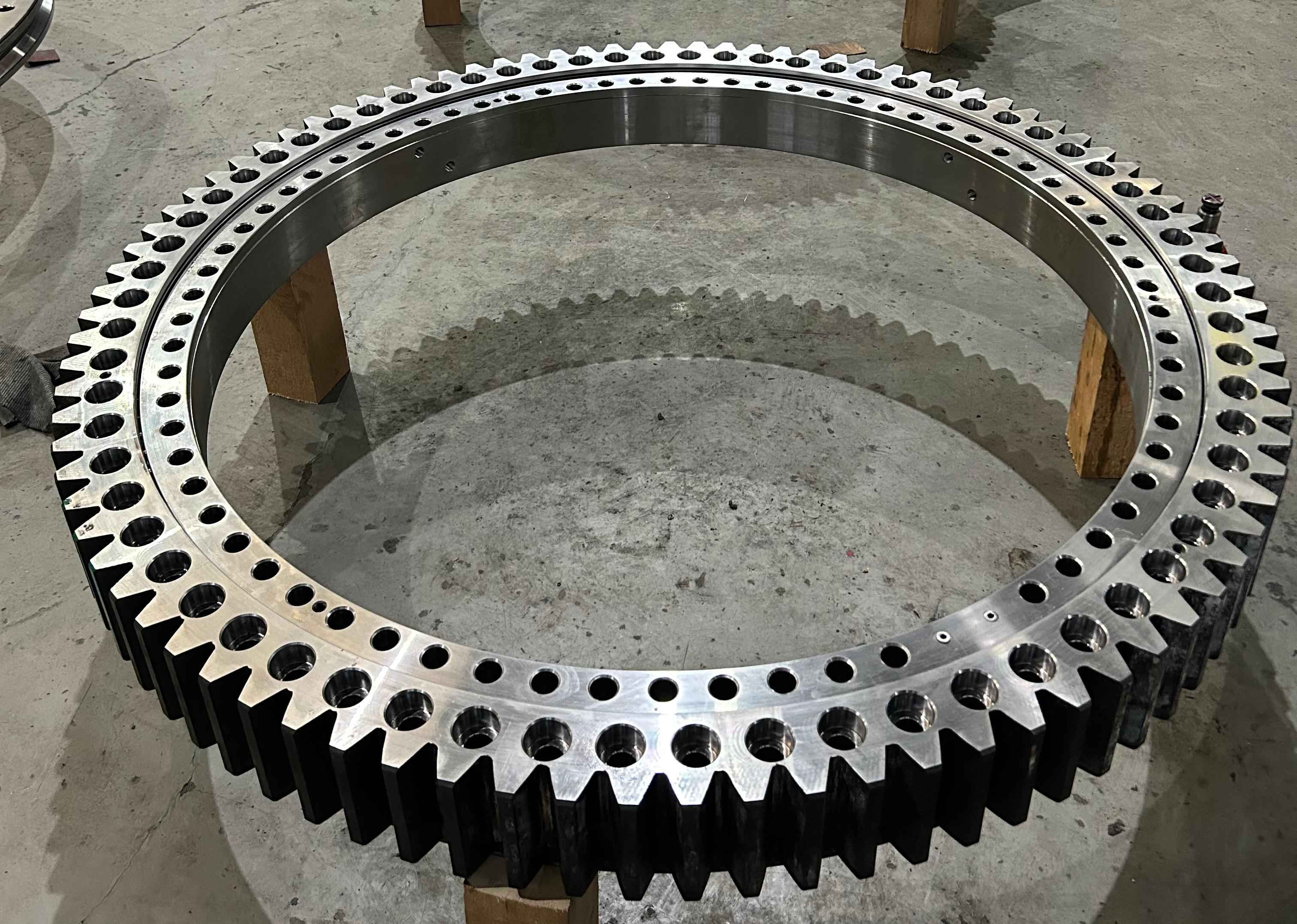
A slewing ring is rarely loaded in one direction only. A boom, platform, tooling head, or rotating frame usually produces vertical force, side force, and a tilting effect at the same time. The bearing must transfer those actions between the rotating structure and the fixed support without excessive deformation or raceway stress.
Conclusion: Select the bearing from the worst realistic operating combination, not from isolated maximum loads listed on separate lines.
Why this matters: A bearing that appears suitable for axial force alone may be unsuitable when radial loading and an overturning moment occur simultaneously. The moment changes the load distribution around the ring. It raises contact loading in one sector while reducing it in another sector. This is why a simple addition of individual load limits is not a valid bearing load calculation.
Best fit: A four point ball design is often considered when equipment needs compact axial support and moderate radial guidance in one bearing location. Examples include compact turntables, aerial work platforms, light lifting equipment, welding positioners, and rotating industrial fixtures.
Limit: If the machine sees repeated shock loads, very high overturning moments, severe radial force, or demanding stiffness requirements, a roller-based arrangement may be more appropriate. Engineers should compare alternatives such as Cross Roller Slewing Bearings or Three Row Roller Slewing Bearings before fixing the architecture.
| Load component | What creates it in practice | What it affects | Risk when assessed separately |
|---|---|---|---|
| Axial load | Dead weight, payload, vertical process force | Ball contact loading and bolt tension or compression | The designer may miss added stress caused by moment loading |
| Radial load | Side thrust, wind, off-center drive force, guide force | Local raceway loading and ring guidance | Side force can reduce running quality if support stiffness is low |
| Overturning moment load | Offset payload, boom reach, elevated center of gravity | Load concentration across opposite bearing sectors | One-sided overload may occur even at moderate axial load |
| Combined operating case | All forces acting during motion or process duty | Actual bearing life, safety margin, and mounting demand | Selection can be based on an unrealistic favorable condition |
How axial, radial, and overturning moment forces follow separate paths through four raceway contact points
The defining feature of this ball bearing architecture is its raceway form. Each ball contacts the raceway system at four potential locations. The contact arrangement permits the ring to react force in more than one direction and gives the bearing its ability to carry axial radial loads and moment loading within one assembly.
However, “four point contact” does not mean every point carries an equal share at every instant. The active contact zones depend on the direction and proportion of the applied forces, the internal clearance, ring deformation, and the stiffness of the connected structures.
| Applied force | Primary load path through the bearing | Practical effect | What goes wrong if underestimated |
|---|---|---|---|
| Axial force downward | Balls transfer force through the contact pair positioned to resist the applied thrust direction | The rotating ring is supported against vertical separation or compression | Raceway contacts can become overloaded on the loaded side |
| Axial force reversal | The opposing contact pair becomes active as thrust direction changes | The bearing can resist uplift or reverse thrust within its rated operating condition | Unplanned reversal can expose insufficient preload or unsuitable clearance |
| Radial force | Ball contacts transfer side force between inner and outer rings around the loaded circumference | The ring remains guided against lateral displacement | Localized edge loading and poor rotation can result from weak support structures |
| Overturning moment | Opposite sectors of the bearing develop opposing reactions through their raceway contact points | One side carries increased compression while the other side may unload or carry reverse reaction | High local contact stress and bolt load variation can occur |
| Combined load case | Axial, radial, and moment reactions overlap around the circumference | The highest loaded zone governs the selection | Using separate ratings can lead to a bearing that is too small |
Axial force path: When vertical force acts on the rotating structure, balls press into the raceway contacts oriented to oppose that force. The load moves from one ring, through the balls, and into the mating ring and mounting frame. If the force direction reverses, the opposing contacts must react the load. This is useful for equipment that experiences uplift, varying payload direction, or changing process forces.
Radial force path: Radial force acts sideways relative to the bearing axis. The loaded zone around the ring transfers that side force through ball-to-raceway contact. Radial capacity is influenced by ring diameter, ball arrangement, raceway geometry, support rigidity, and the direction of force relative to the installed gear and drive components.
Moment force path: An overturning moment tries to tilt one ring relative to the other. The ring does not resist that tilt at one point alone. Instead, the moment produces a reaction couple across opposed areas of the raceway. One sector becomes more heavily loaded while the opposite sector experiences reduced loading or reverse loading. This concentration is often the governing condition for slewing ring design.
Selection limit: A four point arrangement works well when the combination remains within the supplier’s approved load envelope. It should not be selected solely because it can theoretically carry all three load directions. The magnitude, repetition, shock level, and required rotational accuracy still decide whether it is suitable.
Use the bearing architecture that matches the machine duty
Engineers should compare bearing types according to the duty rather than selecting a ball arrangement by default. The table below provides an early-stage screening method. Final selection still requires the actual load spectrum, mounting details, duty cycle, rotation speed, and environmental conditions.
| Bearing option | Where it fits | Main advantage | When it may not fit |
|---|---|---|---|
| Four point ball arrangement | Compact machinery with combined thrust, radial force, and moderate moment | Supports multiple load directions in one ring structure | May not suit repeated high shock or very high moment duty |
| Double row ball arrangement | Applications requiring higher ball count and greater load distribution | Can provide improved capacity through multiple ball rows | May require more installation space and a different ring layout |
| Cross roller arrangement | Positioning equipment requiring high rotational accuracy and stiffness | Rollers can support demanding combined loading conditions | May be unnecessary for simple, lower-duty rotation |
| Three row roller arrangement | Heavy lifting and large overturning moment applications | Separate roller rows can be assigned to different load directions | Usually not the most economical choice for light equipment |
A Four Point Contact Ball Slewing Bearing is usually a sound candidate where installation space is limited and one bearing must handle thrust, lateral force, and tilting action. It is less suitable when the design requirement is driven mainly by extreme moment resistance, high structural stiffness, or severe impact loading.
LTZC supports customized bearing solutions based on working conditions, existing drawings, and technical specifications. Material selection can be matched to the service environment. GCr15 is commonly used where hardness, wear resistance, and strength are required, while AISI 440C may be considered where corrosion resistance is a key requirement. Material choice alone does not correct an unsuitable load architecture.
Check the mounting structure before approving the bearing
A bearing is only as stable as its connected structures. Even a correctly sized ring can develop uneven loading if the machine frame, flange, or support plate bends excessively. Mounting surface stiffness directly affects how evenly the raceway contact points share load around the circumference.
Conclusion: Treat the bearing, bolts, mounting faces, and surrounding steel structure as one load-transfer system.
Why this matters: An uneven mounting face can distort the rings after bolt tightening. A flexible support can change the ring shape during operation. Both conditions concentrate load into a smaller section of the raceway and can create irregular running resistance.
Best fit: This review is especially necessary for welded frames, thin fabricated bases, long boom structures, and equipment with a large offset load.
Limit: A stiff mounting structure does not compensate for an undersized bearing or an incorrect duty assumption. It only allows a suitable bearing to perform as intended.
Mounting review checklist
- Confirm that the ring support face is flat, clean, and free from weld spatter or paint buildup.
- Check that the mounting flange provides support around the intended circumference rather than at isolated pads.
- Review bolt quantity, bolt size, bolt grade, tightening method, and inspection access with the bearing supplier.
- Identify all load directions, including reverse axial force and side load during acceleration or braking.
- Confirm whether the drive pinion introduces radial force into the geared ring.
- Evaluate frame deflection at maximum reach, maximum payload, and worst operating position.
- Plan lubrication access and inspection access before enclosing the bearing.
For installation planning, review LTZC guidance on bearing installation. Installation condition can influence service behavior just as much as the ring selection.
Avoid these common load-selection mistakes
- Using payload weight as the only input. This misses boom reach, tooling offset, wind, acceleration, and process force. Use the force location and direction to calculate the actual overturning moment load.
- Checking maximum loads one by one. Axial, radial, and moment loads must be assessed as combined operating cases. The governing case may occur during slewing, braking, or an off-center work position.
- Ignoring force reversal. A platform can see downward gravity load while travel, lifting, or tooling action creates reverse axial force. State both directions in the request.
- Assuming the ring can correct a flexible frame. The bearing transfers load; it does not make an insufficient support structure rigid.
- Selecting from outside diameter alone. Ring size does not define raceway capacity, bolt demand, gear requirements, or permissible moment loading.
- Leaving the gear drive out of the calculation. Pinion force, braking torque, and gear engagement can add radial and tangential reactions to the bearing system.
- Specifying only static load. Repeated rotation, starts, stops, vibration, and shock affect service conditions and should be stated during selection.
Prepare a usable technical request for bearing selection
A supplier can assess a combined load case more efficiently when the request includes complete machine data. This reduces revisions and helps determine whether a ball slewing bearing is appropriate or whether another arrangement should be evaluated.
- Define the rotating structure. Provide a drawing that identifies the fixed ring, rotating ring, mounting interfaces, and gear location.
- List all applied forces. State axial force, radial force, tangential force, and each force direction.
- State force locations. Give the distance from the bearing centerline for payloads, cylinders, tools, booms, and drive components.
- Identify the worst operating positions. Include maximum reach, elevated load position, acceleration, braking, and any reverse-load event.
- Describe duty. State rotation pattern, operating frequency, expected service environment, contamination exposure, and lubrication plan.
- Provide installation details. Include mounting plate dimensions, bolt circle constraints, allowable ring size, gear requirement, and access limitations.
- Set performance priorities. Clarify whether capacity, stiffness, rotation accuracy, corrosion resistance, compact size, or delivery timing has the highest priority.
LTZC has operated since 1992 and manufactures bearing products within a 20,000 m² facility. Our quality management system is certified to ISO9001:2015, with ISO14001:2015 and ISO45001:2018 also listed in our certifications. We offer no MOQ and a stated delivery range of 30 to 90 days, subject to the required bearing design and production arrangement.
For context on larger engineered work, LTZC delivered an integrated three-row roller slewing ring with an outer diameter of 10.87 meters in 2024 for 2,000 ton fixed lifting equipment. That project uses a different bearing architecture from a four point ball design, but it demonstrates why bearing type must follow the real load path rather than a general product preference. LTZC also produced an integrated bearing with an outer diameter of 8.445 meters for a crane industry client in South Korea during 2024.
Make the final decision from the governing load combination
The right question is not simply whether a four point ball ring can carry axial, radial, and moment loads. It can. The selection question is whether its contact arrangement, ring size, raceway capacity, mounting structure, and bolt connection are suitable for the highest combined operating condition.
Choose this architecture when the machine needs a compact bearing solution for multi-direction loading and the calculated load envelope remains appropriate for ball raceways. Consider other arrangements when extreme moment, repeated shock, very high stiffness demand, or exceptional radial loading controls the design. For special geometries, LTZC can review drawings for Customized Bearings and non-standard bearing requirements.
Submit your drawings and combined load data to request selection advice for your application.