WhatsApp
 jessica.chai@ltzzc.com
 0086-379-69950051

How a Ship Loader Slewing Bearing Handles Bulk Loads
What loads actually reach the turning joint when a ship loader swings a loaded boom over a vessel? The answer is more involved than the conveyor payload alone. A Ship Loader Slewing Bearing must carry forces from the boom structure, conveyor, chute, counterweight, wind exposure, starting and stopping motion, and the drive system that rotates the upper structure.
For early-stage engineering evaluation, the first task is not choosing a bearing catalog size. It is defining the real load paths and operating positions. A bearing that looks suitable under a static payload can be unsuitable when the boom rotates, brakes, or works at an offset angle. Bulk material handling equipment needs a bearing arrangement that matches the complete machine structure, mounting interface, and drive layout.
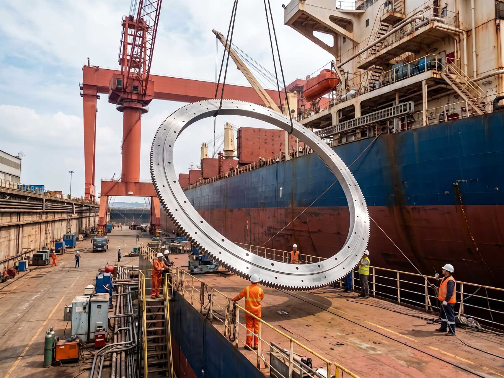
Start with the load path instead of the bearing diameter
The rotating portion of a ship loader typically includes the boom, conveyor components, discharge chute, operator equipment, access platforms, and counterweight. These parts transfer force through the rotating frame and into the bearing rings. From there, the lower ring transfers the reaction into the fixed support structure.
The useful engineering question is: where does each force enter the structure, and how far is it from the bearing center? Distance changes the resulting moment. A moderate vertical load acting far out on the boom can create a demanding overturning moment at the bearing interface.
Define the following operating conditions before requesting a bearing proposal:
Empty boom position: Establishes the baseline dead weight, counterweight effect, and structural balance.
Loaded conveying position: Shows the working reaction from material, belt, idlers, chute, and boom deflection.
Maximum outreach position: Often produces a high moment because the center of gravity is farther from the turning center.
Minimum outreach position: May shift the center of gravity toward the support frame and change ring loading distribution.
Starting and stopping rotation: Introduces acceleration and braking effects that static calculations do not show.
Parked condition: Requires review of wind-related loading and any locking or holding arrangement used by the machine.
The conclusion is straightforward: select from a defined load envelope, not one favorable condition. This approach fits new loader design, structural upgrades, and replacement projects where the original machine duty has changed. It does not replace verification by the equipment designer, because the supporting structure and duty cycle remain part of the bearing system.
For a general review of available ring arrangements, see our precision slewing bearing range. The final configuration should still be based on the actual machine loads and interface drawings.
How radial load, overturning moment, and gear drive forces combine during boom rotation
During slewing, radial load, overturning moment, and gear drive forces do not act separately. They arrive at the bearing and its mounting structure at the same time, often with different directions as the boom rotates. The bearing must transmit these combined reactions while keeping the gear mesh and mounting surfaces within the machine designer’s allowable conditions.
| Load effect | What creates it on a ship loader | What it affects in practice | What can happen if it is underestimated |
|---|---|---|---|
| Radial bearing load | Horizontal actions from boom motion, conveyor alignment effects, structural side forces, and rotating-frame reactions | Loads the bearing in its radial direction and can influence ring position relative to the drive pinion | Ring movement can disturb gear engagement, increase localized raceway demand, and place extra stress on the supporting structure |
| Overturning moment | Vertical weight acting at boom outreach, changing material position, counterweight balance, and external forces on the boom | Creates an uneven load distribution around the bearing raceways and mounting bolts | A design based only on total weight may miss high local reactions at the most heavily loaded ring sector |
| Gear drive forces | Pinion torque, tangential tooth force, radial tooth reaction, acceleration, deceleration, and drive reversal | Acts locally where the pinion engages the ring gear and affects tooth contact conditions | Poor gear alignment or insufficient structural stiffness can lead to uneven tooth contact and unstable rotation |
| Combined response | Boom rotation while carrying material, particularly during change of speed or direction | Changes raceway contact distribution, bolt loading, structural deflection, and gear mesh at once | Checking each force alone can hide the governing operating position |
In practice, the overturning moment usually governs the bearing reaction pattern, while radial effects and gear drive forces can govern interface behavior at particular boom angles. The right conclusion is not that one load category always controls. The governing condition depends on the boom geometry, rotating mass, support frame stiffness, drive position, and operating sequence.
A useful example is a loader rotating with material on the belt at extended boom outreach. The vertical load and outreach create a high moment. At the same time, the drive pinion applies tangential force to rotate the structure. If the machine is then stopped, the drive force reverses in direction while the moment remains. The bearing rings, bolts, gear teeth, and support frame all see the combined event.
This scenario fits loaders that slew during conveying or position the boom repeatedly during a loading cycle. It does not apply in the same way to equipment that only rotates when empty, although the parked and maintenance conditions still require review.

Choose the ring arrangement around machine behavior
Different ring constructions distribute load through different rolling element paths and ring geometries. The correct choice depends on the dominant combined loading, available mounting diameter, structural stiffness, gear arrangement, and service access requirements. It should not be decided from bearing diameter alone.
| Arrangement consideration | When it may fit | Why engineers consider it | Limit to check |
|---|---|---|---|
| Single row ball arrangement | Moderate combined loading with a space-conscious equipment layout | Can provide a practical integrated solution for axial, radial, and moment reactions | Load capacity and contact conditions must be verified for the actual duty envelope |
| Crossed roller arrangement | Applications needing controlled rotational behavior under combined reactions | Roller orientation can support multi-directional loading requirements | Mounting accuracy and support stiffness become especially important |
| Multi row roller arrangement | Large loaders with demanding vertical and moment reactions | Separate rolling paths can be arranged to address different load directions | The surrounding structure must provide suitable support around the full mounting circumference |
| External or internal gear ring | Where the drive layout dictates pinion access and guarding position | Integrates rotation drive with the bearing assembly | Pinion position, backlash setting, tooth contact, and maintenance access require coordinated design |
An integrated slewing ring gear can reduce the number of separate rotating interfaces, but it also makes gear alignment part of the bearing installation plan. This is suitable when the loader drive is designed around a pinion engaging the ring. It may not fit a design using a separate gear train or another rotation architecture.
LTZC Bearings Co.,Ltd. supplies customized bearing solutions based on working conditions, existing designs, and technical specifications. That is useful when a ship loader upgrade has nonstandard mounting dimensions, a revised boom arrangement, or a drive layout that cannot use an off-the-shelf ring. Customization still requires complete engineering inputs; it cannot compensate for missing load cases or an undefined support structure.
Check the mounting structure before approving the bearing
A slewing ring is only as effective as the surfaces supporting it. The bearing rings need stable, adequately prepared mounting faces so that the intended load distribution is not distorted by local gaps, uneven support, or structural deformation.
Bearing mounting surfaces should be reviewed together with the bearing drawing. Engineering teams should provide the upper and lower interface geometry, bolt arrangement, support ring shape, nearby weld positions, and any local stiffeners. This allows the bearing supplier and machine designer to identify conflicts before fabrication or installation.
Use the following procedure during early technical evaluation:
List every operating position, including loaded slewing, empty slewing, stopping, parked, and maintenance conditions.
Identify the rotating mass and the approximate center of gravity for each position.
Record the boom outreach and the direction of the resulting reactions relative to the bearing center.
Define the rotation drive arrangement, including pinion location, drive torque information from the drive supplier, and planned braking behavior.
Prepare upper and lower mounting drawings showing bolt locations, support geometry, and access constraints.
Review ring type, gear position, bolt design responsibility, and lubrication access with the bearing supplier.
Confirm the installation sequence, gear mesh adjustment method, and inspection points before releasing the design.
This procedure suits both a new-build machine and a replacement bearing project. For a replacement, add a structural inspection of the existing pedestal and rotating frame. Reusing the previous bearing dimensions without checking deformation, bolt condition, and changed duty can repeat the original problem.
Our bearing installation guidance can support planning for mounting, lubrication, and inspection. Site procedures must still follow the machine manufacturer’s safety rules and the approved engineering documentation.
Avoid selection mistakes that create avoidable downtime
Bulk loader bearing problems often begin during specification, not after installation. The following mistakes are common because they simplify the system too early.
Using payload alone as the design basis: This ignores boom self-weight, counterweight, equipment weight, outreach, and driving forces. Use a complete rotating-structure load model instead.
Checking only one boom angle: The loaded outreach condition may govern the moment, while another angle may create a more difficult gear mesh condition. Review several defined positions.
Separating bearing and drive selection: Gear drive forces enter the ring locally. Coordinate the bearing supplier, structural designer, and drive supplier before finalizing the pinion arrangement.
Ignoring support stiffness: A bearing can be correctly specified but perform poorly if the mounting frame flexes beyond the assumptions used in the selection review. Assess the full support path.
Leaving installation access unresolved: If technicians cannot reach bolts, grease points, gear mesh points, or inspection locations, correct maintenance becomes difficult. Include access in the layout stage.
Ordering before drawings are stable: Changes to bolt circles, gear location, or ring dimensions can affect the entire interface. Release the order after the required design inputs are confirmed.
The conclusion is to treat the bearing, drive, and structure as one assembly. This is most relevant for high-utilization ship loaders and upgraded equipment. A simpler machine with low rotation duty may have fewer interacting conditions, but it still needs confirmation of load paths and mounting support.
Prepare a supplier data package that leads to a usable proposal
A clear request package reduces repeated questions and helps the supplier assess whether a standard arrangement or custom design is appropriate. Engineering teams should submit information that describes the machine, not only a desired ring diameter.
| Information to submit | Why it matters | Decision it supports |
|---|---|---|
| General assembly drawing | Shows boom position, rotating frame, pedestal, and installation space | Ring envelope and gear orientation |
| Load cases by operating position | Shows axial, radial, and moment reactions under realistic machine conditions | Bearing arrangement and application review |
| Drive system information | Defines pinion interaction and expected gear drive forces | Gear form, gear location, and drive interface |
| Mounting structure drawings | Shows the bearing support path and bolt interface | Mounting review and installation planning |
| Duty and maintenance requirements | Clarifies operating frequency, inspection access, and lubrication approach | Practical service planning |
LTZC operates under ISO9001:2015, ISO14001:2015, and ISO45001:2018 management system certifications, with ISO, CCS, and ABS certifications stated in its company information. These credentials support a documented quality and management framework; they do not remove the need for project-specific engineering validation.
For procurement planning, LTZC states a delivery window of 30–90 days and no MOQ. Those terms can help where a project needs a custom evaluation, a replacement unit, or a limited procurement quantity. Delivery planning should be confirmed against the approved drawings, selected configuration, and current order requirements.
For related rotation assemblies, review LTZC Slewing Drives where the machine concept calls for an integrated drive approach. For unusual interfaces or replacement dimensions, non-standard bearings may be relevant after the technical data package is complete.
Submit your ship loader drawings and load cases to request selection advice and a project-specific quotation.