WhatsApp
 jessica.chai@ltzzc.com
 0086-379-69950051

How Do Robotic Slewing Bearings Control Joint Runout?
A robot joint can have a precise encoder and a rigid reducer and still miss its repeatability target. The cause is often the bearing between the fixed and rotating structure. A robotic slewing bearing controls runout through raceway geometry, internal clearance or preload, and how well its rings keep their shape after mounting. Each of the three runout components reaches the end-effector by a different route. Treating them as one "runout" number is where most early-stage specifications go wrong.
This article is for engineers defining a rotary joint, such as a base axis, a waist or a turntable stage. It shows how to turn a positioning target into separate axial, radial and tilting limits. If you are still choosing a bearing family, our pages on Robotics and Automation Slewing Bearings and thin section bearing designs show the typical options.
What "joint runout" means in a slewing bearing
Runout is the movement of a ring surface relative to its ideal position during one rotation. In a slewing bearing it splits into three parts, and each one has its own cause.
Axial runout: the mounting face moves up and down along the rotation axis as the joint turns.
Radial runout: the rotation center shifts sideways, so the rotating part orbits slightly instead of spinning on a fixed axis.
Tilting runout: the rotation axis itself rocks. It is driven by moment load and by clearance or elastic yield in the raceway contact.
The bearing controls these through three mechanisms. First, raceway and ring accuracy set the starting geometry. Second, preload or clearance sets how much the rings can shift when load direction changes. Third, ring stiffness decides whether the bearing keeps its shape once bolted to a real structure. Material also matters for long-term stability. GCr15 offers high hardness and wear resistance, and 42CrMo suits heavier loads. Wear on a raceway slowly turns a good initial runout figure into a worse one.
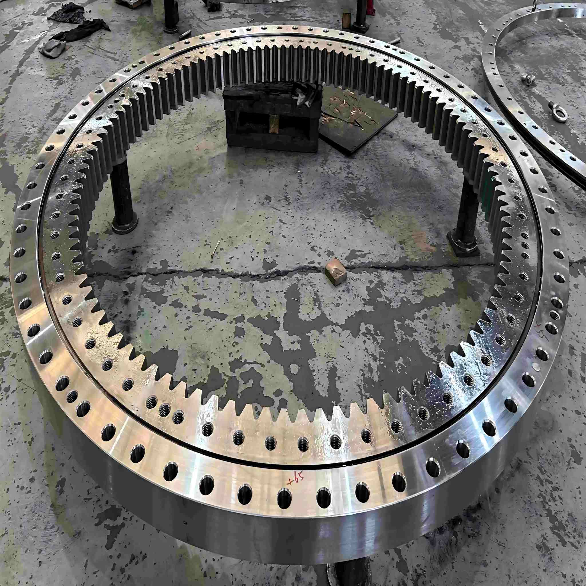
Axial, radial and tilting-moment runout sources and their effect on robot repeatability
The table separates the three components by origin, by how each reaches the tool point, and by whether it can be calibrated out. The last column matters most. A runout that repeats every revolution can often be compensated in the robot model. A runout that changes with load, temperature or wear cannot.
| Runout type | Typical sources | Effect at the end-effector | Can it be calibrated out? |
|---|---|---|---|
| Axial | Raceway face flatness, mounting-face squareness, uneven bolt preload, thermal growth | Vertical offset of the rotating structure. It is not multiplied by arm length unless it also tilts the axis. | Partly. The fixed-phase part is repeatable, the load-dependent part is not. |
| Radial | Ring roundness, bore or seat eccentricity, radial clearance, shifting under side load | Sideways shift of the rotation center. It transfers roughly one-to-one to the tool point. | Partly. A fixed eccentricity can be modeled, a clearance-driven shift cannot. |
| Tilting (moment) | Clearance under overturning moment, raceway contact yield, ring deformation after mounting | Axis rocking. The error scales with reach, so a small angle becomes a large tool-point error. | Rarely. It changes with payload, pose and acceleration. |
Tilting is usually the dominant contributor on long-reach joints, even when the axial and radial figures on the datasheet look small. That is why a joint with good measured runout in a test fixture can still show poor repeatability in the cell. The fixture applies no overturning moment.
How preload, clearance and mounting interact
These attributes do not act independently. Tightening one improves a runout component while hurting another property.
Preload. Eliminates clearance, so tilt and radial shift under changing loads shrink. The trade-off is higher friction torque, more heat and faster wear. It fits joints with reversing loads and tight repeatability. It does not suit joints that must run at high speed with limited motor torque.
Clearance. Gives lower friction and tolerance for mounting error. The cost is play that appears as hysteresis whenever the load direction flips. It fits slow, one-direction-dominant loads and is a poor fit for pick-and-place with changing moment direction.
Ring stiffness. Thin-section rings save weight and bore space but conform to the surface they are bolted to. A face that is a few hundredths of a millimeter out of flat can be pulled into the raceway as axial and tilting runout. A thicker ring resists this but adds mass to the joint.
Contact design. A cross roller slewing bearing carries axial, radial and moment loads in one raceway pair and is common in compact joints. Line contact gives high stiffness. The trade-off is higher sensitivity to mounting-surface error and a need to set preload carefully.
The practical point is that a bearing datasheet value for runout is measured under defined conditions: a specific mounting, no external moment, a specific temperature. The same bearing on a different housing will behave differently. Do not compare runout figures from different suppliers unless the test conditions match.
Worked example: converting a repeatability target into runout limits
The numbers below are illustrative geometry, not an LTZC specification. Suppose a joint has a tool reach of 1,000 mm from the rotation axis and a bearing measuring circle of 400 mm diameter. The target is ±0.05 mm of repeatability, and the bearing may use at most half of it.
Set the bearing budget. Half of ±0.05 mm leaves ±0.025 mm at the tool point for the bearing. Reducer, structure deflection and encoder take the rest.
Convert tilt to angle. A tilting runout of 0.02 mm measured across the 400 mm circle equals 0.02 / 400 = 0.00005 rad.
Project to the tool. 0.00005 rad × 1,000 mm = 0.05 mm. This single component already exceeds the whole bearing budget.
Revise the limit. To stay within 0.025 mm, tilt must stay below roughly 0.00002 rad. On the 400 mm circle that is about 0.01 mm of axial difference, before any radial contribution.
Add radial. Radial runout adds nearly one-to-one, so it must fit in what the tilt leaves over. Allocate the budget between them rather than quoting one total.
The lesson: a limit that looks fine as a bearing figure can fail once it is multiplied by reach. Run this calculation for your own reach and measuring diameter before you request a tolerance class.
Common misunderstandings and what to ask the supplier for
Mistakes that change the outcome
Assuming lower runout always means better repeatability. Repeatable runout can be calibrated out. Unstable runout, which changes with load or wear, is the real problem.
Specifying a single "runout" value. Axial, radial and tilting limits should be written separately, with the measuring diameter stated.
Ignoring the mounting structure. A precise bearing on an uneven face loses its accuracy. Specify flatness and squareness of the mating surfaces.
Treating preload as free. It reduces play but raises friction and heat, which feeds back into the motor and thermal drift.
Skipping the installation step. Bolt sequence and torque change ring shape. Follow written bearing installation guidance.
Evidence worth requesting
Axial, radial and tilting runout reported separately, with measuring diameter and mounting condition.
Raceway and ring dimensional inspection records for your batch.
Preload or clearance setting and its torque consequence.
Material and heat treatment of the rings, such as GCr15 or 42CrMo.
A statement of conditions under which the quoted figures no longer apply, such as high moment or temperature shift.
A report like this shows what the bearing delivered at acceptance. It does not predict behaviour in your cell, which depends on your housing and load cycle. Request it, then confirm in a prototype test with the real structure.
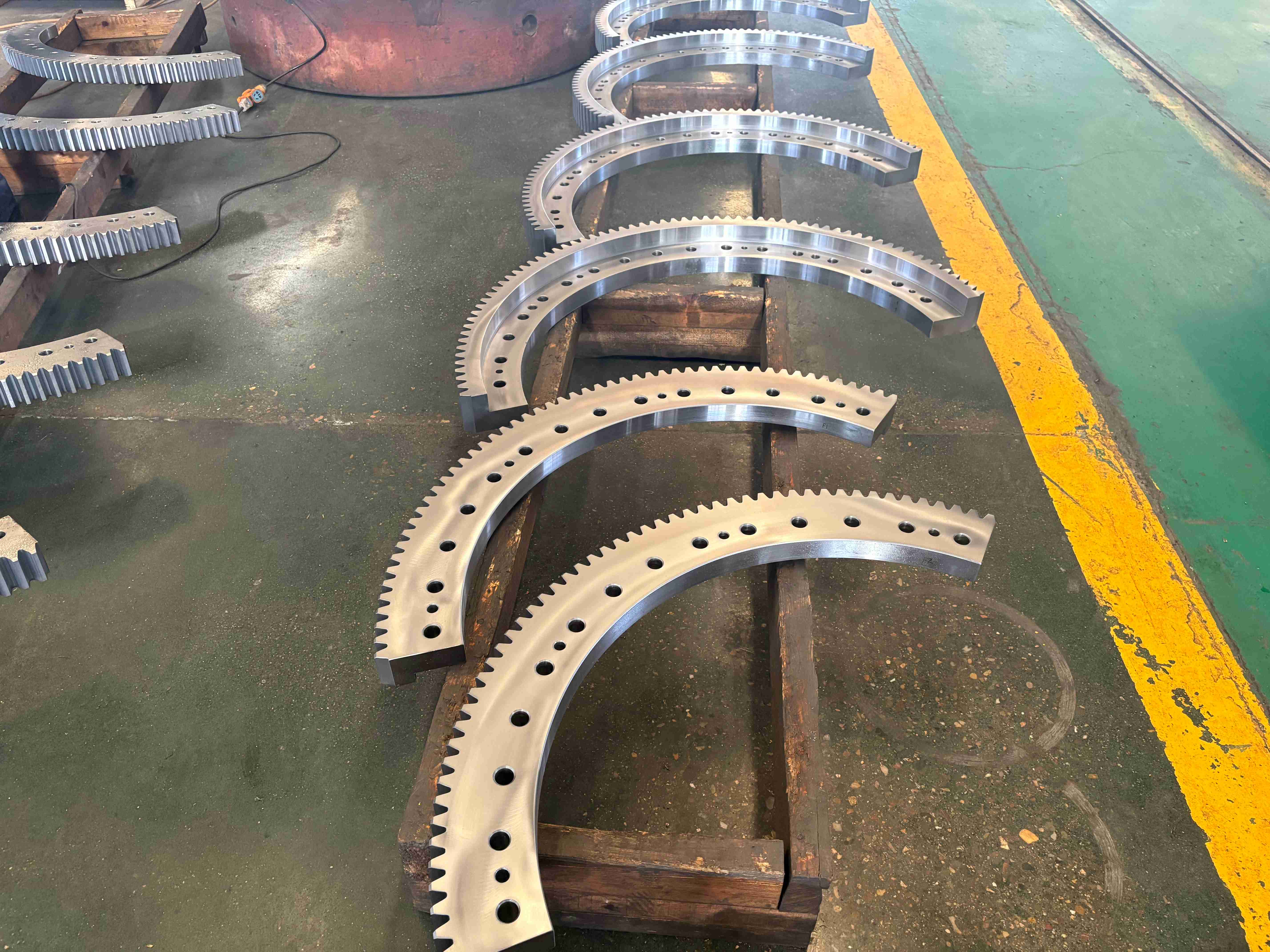
Where precision manufacturing experience applies
LTZC has made precision bearing and gear components since 1992 at a 20,000 m² facility, and its quality system is certified to ISO9001:2015. The cases below involve different products, but they show work where geometry control was the deciding factor.
8-meter high-precision segmented gear rings supplied to Wuhan Heavy Industry for the vertical friction stir welding system of a key national project.
A 3-meter-diameter turntable bearing that held up the main torch tower at the opening ceremony of the World Military Olympic Games.
These are not robot joints, and we do not present them as such. They show experience holding geometry on large rotating structures. For compact robot joints, the process is the same: define the three runout components, set the measuring conditions and verify with real mounting.
When standard sizes do not fit, customized bearings can be built from your working conditions and drawings. There is no MOQ, and delivery runs 30 to 90 days depending on the design. For comparing families first, our bearing selection guide lists the load and stiffness factors. If a joint shows unexplained repeatability drift, we also provide fault analysis and on-site support.
Send us your joint drawing, reach, payload and repeatability target, and we will suggest runout limits and a bearing configuration to check against your design.