WhatsApp
 jessica.chai@ltzzc.com
 0086-379-69950051

How to Specify a Large Diameter Slewing Ring for Reliable Gear Performance
Which gear configuration goes on a large diameter slewing ring when the drive motor, the counterweight, and the service hatch all need the same real estate? This is the question most mechanical designers hit once the ring diameter passes 1.5 meters and the drive layout stops being a simple bolt-pattern exercise. Get the gear placement wrong at the concept stage, and you end up redesigning the housing after the quote comes back. This guide walks through the decisions that need to be locked before you send drawings out for pricing.
A large diameter slewing ring is not just a bigger bearing — the gear geometry, tooth hardening, and mesh clearance all scale differently than they do on smaller rings, and the tolerances stack up faster. Below, we break down internal versus external versus unguided options, show how tooth placement changes torque transfer and maintenance access, and give you a checklist to run before requesting detailed drawings.
Internal, External, and Unguided Gear Configurations Compared
Three gear arrangements cover almost every slewing application: internal gear, external gear, and no gear at all (unguided, driven by a separate chain, hydraulic cylinder, or friction drive). Each has a different footprint, cost profile, and failure mode.
| Configuration | Best Fit | Torque Handling | Maintenance Access | Typical Limit |
|---|---|---|---|---|
| Internal gear | Cranes, excavators, compact turntables | High, teeth protected from debris | Requires opening the housing or inspection port | Harder to inspect tooth wear in the field |
| External gear | Wind turbines, ship cranes, solar trackers | High, but exposed teeth see more contamination | Easy visual inspection, grease access from outside | Needs a seal or cover in dusty or marine sites |
| Unguided (no gear) | Low-speed, low-torque swing applications | Lower, relies on external drive mechanism | Simplest access, nothing to re-mesh | Not suitable where continuous rotation under load is required |
Internal gears sit protected inside the ring, which matters for equipment working in sand, concrete dust, or agricultural debris. External gears trade that protection for faster inspection and lower-cost tooling during manufacture, since the hobbing process is more accessible on an outside diameter. An unguided precision slewing bearing skips gearing entirely and is paired with a separate drive mechanism — this works for turntables and displays where torque demand is modest but adds cost and complexity if your application later needs motorized rotation.
Gear Placement and Tooth Geometry: Drive Layout, Torque Transfer, and Maintenance Access
Where the gear sits relative to the raceway changes three things that designers often treat as separate problems but should solve together: how the drive motor mounts, how torque reaches the load, and how a technician gets a wrench in later.
- Single-row gear below the raceway: Keeps the drive motor low and out of the load path, common on crane slew rings. Torque transfer is direct, but the motor housing competes for space with mounting bolts — check bolt circle clearance before finalizing the drive bracket.
- Gear integrated with a double-row raceway: Found on heavier wind and marine applications where axial and moment loads are both high. Torque transfer is stable under combined loading, but tooth replacement means removing the whole assembly from the structure — budget extra downtime for this.
- External gear with top-mounted motor: Common on excavator swing circles. Maintenance access is good since the pinion and motor sit above the structure, but exposed teeth need a cover in abrasive environments or lubrication intervals shorten.
- Unguided ring with separate drive train: No tooth wear to manage at all, but torque transfer depends entirely on the external mechanism's rigidity — any slack in that linkage shows up as backlash at the load.
A practical example: on a 2.2-meter tower crane slew ring, moving the gear from an external to an internal position reduced the exposed tooth surface by roughly 40%, which cut grease consumption but required a larger access port cut into the slewing platform for periodic tooth inspection. That tradeoff — contamination resistance versus inspection convenience — is the core decision point for most large ring gear projects. If your equipment runs in an enclosed housing already, internal gearing usually wins. If the ring sits exposed to the elements and technicians need quick visual checks, external gearing is typically the better call.
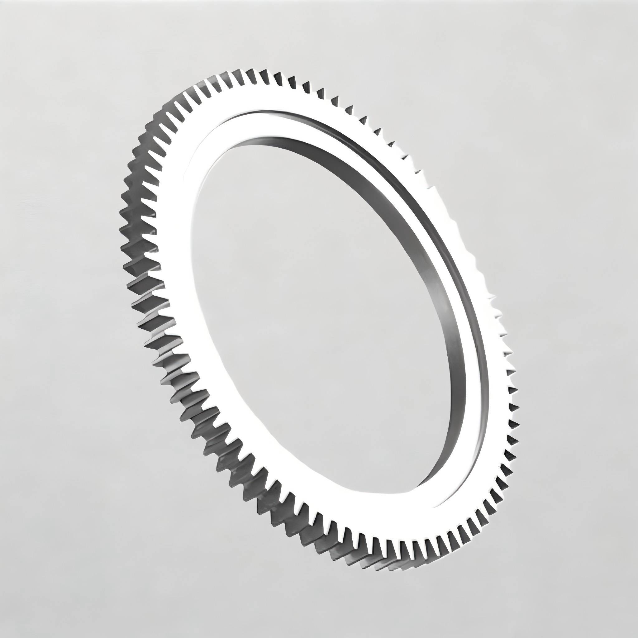
Step-by-Step Process to Specify Your Ring Gear
Follow this sequence before sending drawings to any supplier. Skipping steps is the most common reason quotes come back with the wrong gear type or tooth module.
- Define the load case first. Axial load, radial load, and tilting moment all affect whether you need a single-row, double-row, or crossed-roller design. Without this, gear sizing is guesswork.
- Choose internal, external, or unguided based on environment and inspection access, using the comparison above as a starting point.
- Set the module and tooth count to match your available drive motor and target rotation speed. A finer module reduces noise but lowers torque capacity per tooth.
- Confirm hardening depth and tooth profile. Induction-hardened teeth resist wear longer under continuous duty cycles than flame-hardened alternatives, but cost and lead time differ.
- Check mounting bolt pattern against the gear position. Bolt holes and gear teeth should never overlap in the design envelope — this is the single most common clash we see in incoming drawings.
- Specify sealing and lubrication points relative to gear exposure, especially for external configurations operating outdoors.
- Request tolerance class and runout limits appropriate to your rotation speed. Slower turntables tolerate looser runout than fast-indexing applications.
Each of these steps feeds the next — a load case error at step one cascades into a wrong module choice at step three, and that mistake is expensive to catch after the ring gear has been cut.
Common Specification Mistakes That Cause Delays
- Specifying tooth module without confirming motor pinion compatibility. Mismatched modules mean the ring gear and drive pinion simply won't mesh, forcing a full respecification.
- Ignoring maintenance access during the concept phase. Internal gears placed too close to a sealed housing wall leave no room for inspection tools later.
- Underspecifying hardness for abrasive environments. Standard case hardening may wear faster than expected in sites with heavy dust or sand, shortening service intervals.
- Leaving tolerance class undefined. Without a stated tolerance class, suppliers default to standard commercial tolerances, which may not suit high-precision rotation applications.
- Assuming all slewing rings accept standard flanges. Large diameter rings often need custom flange patterns — confirm this early rather than after drawings are finalized.
Most of these mistakes trace back to treating gear specification as a late-stage detail instead of a design input. Bringing a bearing selection guide into the concept phase, rather than after structural layout is frozen, avoids most of this rework.
Material, Tolerance, and Lead Time Checkpoints
Beyond gear type, three technical checkpoints decide whether your supplier can actually build to your drawing without back-and-forth revisions.
| Checkpoint | Why It Matters | When to Flag It |
|---|---|---|
| Steel grade and heat treatment | Determines fatigue life under cyclic loading | Before finalizing ring OD and ID |
| Tooth tolerance class | Affects backlash and noise under load | When drive speed exceeds standard turntable rates |
| Flange and bolt hole pattern | Must align with your structural mounting points | Early, since it affects the whole housing design |
| Production lead time | Typically 30-90 days depending on size and customization | As soon as the project timeline is known |
LTZC works under ISO9001:2015 quality management, with ISO14001:2015 and ISO45001:2018 certification, and products are certified by ISO, CCS, and ABS depending on application. There's no minimum order quantity, which matters for prototype runs or one-off replacement rings where a large batch commitment isn't practical. Delivery typically runs 30 to 90 days depending on size, gear complexity, and material specification.
Buyer's Decision Checklist Before Sending Drawings
- Have you confirmed load case (axial, radial, moment) with actual operating numbers, not estimates?
- Does your gear configuration match your environment — internal for enclosed/dusty conditions, external for easy inspection?
- Has the drive motor pinion module been cross-checked against your proposed ring gear module?
- Is there physical clearance between bolt holes and gear teeth in your current layout?
- Have you specified tolerance class, hardening method, and sealing requirements explicitly?
- Do you need a standard flange, or does your application call for non-standard bearings with a custom flange pattern?
- Have you reviewed bearing installation clearances for the gear position you've chosen?
If every item on that list has an answer, your drawing package is ready for quoting. If any item is still open, it's worth resolving before submission — reworking a large diameter slewing ring after cutting is far more costly than revising a drawing.
For projects involving heavier torque transfer or compact envelopes, a motorized Slewing Drives assembly or a separate slewing ring gear component may fit better than an integrated design — and for applications with tight axial space, a thin section bearing might replace a full slewing ring altogether.
If you have a load case and rough envelope sketched out but haven't settled on internal, external, or unguided gearing yet, send us your drawings or working conditions and we'll help confirm the configuration before you commit to a final design.