WhatsApp
 jessica.chai@ltzzc.com
 0086-379-69950051

How to Specify Industrial Slewing Bearings for Automated Systems
As an engineer with a decade of experience in this field, I've seen countless projects where the success of an entire automated system hinges on the correct specification of its rotational components. Specifying industrial slewing bearings for high-cycle automated machinery is not the same as selecting one for a crane or an excavator. The demands for precision, repeatability, and long operational life are significantly higher. A small oversight in defining parameters like mounting flatness or gear backlash can lead to premature failure, costly downtime, and a loss of production quality. This guide directly addresses the critical questions designers face when integrating these components into automated lines.
At LTZC, our work is guided by a quality management system certified to ISO9001:2015, ensuring that every component meets stringent global standards. We understand that getting the initial design specifications right is the foundation of a reliable system.
Key Performance Parameters for Slewing Bearings in Automation
In automated applications such as robotics, indexing tables, and packaging machinery, performance is measured by consistency over millions of cycles. Unlike heavy equipment where loads are high but cycles are infrequent, automation demands a different set of priorities. The three core considerations are load capacity, rotational accuracy, and speed, but their context changes entirely.
Load Spectrum: While the absolute load might be lower than in a mining application, automated systems often impart complex and rapidly changing tilting moment loads. A robotic arm, for instance, generates a high moment load when extended, which reverses as it moves. The bearing must handle this dynamic load spectrum without developing excessive play over its service life.
Rotational Accuracy and Repeatability: Positional accuracy is paramount. The bearing's runout—both axial and radial—directly impacts the precision of the entire machine. In a welding robot or a semiconductor wafer handler, even a tiny deviation can ruin the product. This requires bearings with minimal clearance or even a specific preload.
Speed and Acceleration: Automated lines prioritize throughput. Bearings must support fast rotational speeds and high acceleration/deceleration ramps without generating excessive heat or experiencing cage failure. This influences the choice of raceway geometry, ball or roller material, and lubrication.
Understanding these distinct demands is the first step. The next is to define the specific operational boundaries, which is where many design teams require clarification.
Specification Boundaries for Automated Production Lines
To ensure reliability in automated production lines, engineers must define clear operational limits. Below are answers to the most common specification questions regarding the physical and operational boundaries of slewing bearings in these demanding environments. These are general engineering guidelines; for specific applications, always consult with a bearing specialist to define exact values for your chosen component, such as a precision slewing bearing.
What is the required mounting flatness?
The flatness of the mounting structure is arguably the most critical factor for bearing performance and life. An uneven surface distorts the bearing raceways when the mounting bolts are torqued, creating tight spots that lead to high friction, increased torque, and rapid wear.
General Guideline: For standard precision bearings (up to 1000 mm diameter), the mounting surface flatness should typically be within 0.05 mm to 0.1 mm.
High-Precision Applications: For high-precision systems like machine tools or robotics, this requirement becomes much stricter, often needing a flatness of 0.025 mm or better.
How to Measure: Use a precision straightedge and feeler gauges or a laser alignment tool across the mounting surface. The surface must be clean and free of burrs.
Consequence of Violation: A non-flat surface can reduce bearing life by over 50% and will void most manufacturer warranties.
How much gear backlash is acceptable?
Gear backlash is the clearance between mating teeth of the bearing's gear and the drive pinion. While some backlash is necessary to prevent jamming and allow for lubrication, excessive backlash reduces positional accuracy.
Standard Industrial Automation: A typical backlash for standard geared slewing rings is between 0.05 mm and 0.15 mm.
Precision Indexing/Robotics: For applications requiring high positional accuracy, a low-backlash or zero-backlash gear is necessary. This is often achieved through specialized gear profiles or by using an adjustable pinion mounting to set the backlash during assembly. A slewing ring gear can be custom-manufactured to meet tight backlash requirements.
Consideration: The specified backlash is for the bearing itself. The final system backlash will also depend on the gearbox and drive motor.
What are the rotational speed limits?
The maximum rotational speed of a slewing bearing is limited by the "DN value" (bearing bore in mm multiplied by speed in RPM) and other factors like load, lubrication, and heat dissipation.
Limiting Factor: The primary constraint is the centrifugal force on the rolling elements and the cage that separates them. High speeds can cause the cage to fail.
Typical Speeds for Large Bearings: For large diameter industrial slewing bearings (e.g., >500 mm), continuous speeds are often limited to 5-10 RPM.
Higher Speed Solutions: For smaller diameters or specialized applications, designs can accommodate higher speeds. This often involves using lighter rolling elements (e.g., ceramic balls), a different cage material (e.g., brass or polymer instead of steel), and specialized lubrication systems. A thin section bearing is often a better choice for high-speed, light-load applications.
How is the duty cycle defined and limited?
The duty cycle describes the operational pattern of the bearing: how long it runs, how long it rests, and the nature of the load during operation. It is critical for calculating bearing life and thermal stability.
Defining the Cycle: A complete duty cycle includes acceleration, constant speed, deceleration, and dwell (rest) periods, along with the load profile (magnitude and direction) at each stage.
Continuous Duty (100%): This is the most demanding scenario, where the bearing rotates under load without significant rest periods. This requires careful thermal management to prevent lubricant breakdown.
Intermittent Duty: More common in automation, where a machine performs a task and then waits. For example, a 40% duty cycle might be 4 seconds of movement followed by 6 seconds of dwell.
Impact on Selection: A bearing specified for intermittent duty may fail quickly if used in a continuous duty application due to overheating. Always specify the full cycle to ensure the bearing's thermal properties are adequate.
Common Specification Mistakes and How to Avoid Them
Correctly interpreting datasheets is only part of the process. Avoiding common oversights during the design phase can prevent significant issues down the line. Here are four frequent mistakes I have helped clients resolve.
Checklist: Avoiding Specification Errors
Mistake: Underestimating Tilting Moment Loads. Many designers focus on axial and radial loads but neglect the tilting moment, which is often the dominant load in applications like robotic arms or satellite dishes.
Solution: Always calculate the maximum tilting moment by considering the load, its distance from the bearing's center, and any dynamic forces from acceleration. Select a bearing based on its moment load capacity curve, not just its axial/radial ratings.Mistake: Ignoring Environmental Factors. A standard, open bearing will fail quickly in a wet, dusty, or corrosive environment. Contaminants can destroy raceways, and temperature extremes can degrade lubrication.
Solution: Specify the operating environment clearly. This dictates the need for seals (e.g., nitrile, Viton), special coatings (e.g., zinc plating), or stainless steel construction.Mistake: Mismatching Gear and Drive Systems. Assuming any standard pinion will work with a geared slewing bearing is a recipe for noise and rapid wear. The gear module, pressure angle, and quality level must be compatible.
Solution: Provide the specifications for your drive pinion when ordering the bearing, or source the pinion and bearing from the same supplier to ensure a perfect match.Mistake: Overlooking Installation Requirements. A high-precision bearing is useless if installed improperly. Uneven torque on mounting bolts, a distorted mounting surface, or misalignment can cause immediate damage.
Solution: Always follow the recommended bearing installation procedure, including using a calibrated torque wrench and following the specified bolt-tightening pattern (typically a star pattern).
Selecting the Right Bearing Structure for Your Application
Different internal geometries offer distinct advantages in load capacity and stiffness. Choosing the correct structure is a trade-off between performance, size, and cost. For automation, the most common choices are four-point contact ball bearings and crossed roller bearings.
| Bearing Type | Primary Load Capacity | Rotational Accuracy | Typical Automation Application |
|---|---|---|---|
| Single-Row Four-Point Contact Ball | Good axial and moderate moment load capacity. Lower radial capacity. | Standard to good. Ideal for most industrial automation. | Indexing tables, packaging machines, light-duty robotics. |
| Single-Row Crossed Roller | Excellent capacity for axial, radial, and moment loads. Very rigid. | Very high. Minimal deflection under load. | Precision machine tool tables, medical scanners, high-payload robots. |
| Double-Row Ball | Very high axial and moment load capacity. | Standard. Higher friction than single-row designs. | Stacker cranes, welding positioners, heavy-duty rotators. |
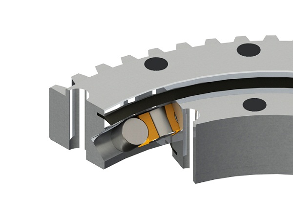
The four-point contact bearing is a versatile and cost-effective workhorse for many automated systems. However, when rigidity and precision are the top priorities, a crossed roller bearing provides superior performance due to its line contact (versus point contact) in the raceway.
Our Customization and Quality Assurance Commitment
Standard catalog bearings do not always meet the unique demands of a specialized automated system. We recognize this and have built our capabilities around providing non-standard bearings tailored to your exact working conditions and technical specifications. Whether you need specific materials, unique dimensions, or integrated features, our engineering team can develop a solution.
Our commitment to quality is validated by multiple certifications, including ISO9001:2015 for quality management, ISO14001:2015 for environmental management, and ISO45001:2018 for occupational health and safety. We are also certified by the China Classification Society (CCS) and the American Bureau of Shipping (ABS) for marine and offshore applications, a testament to the reliability of our products in harsh environments.
For OEMs developing new machinery or specialized production lines, we offer the flexibility of no minimum order quantity (MOQ). This allows you to procure single prototypes or small batches for testing without a large financial commitment. With a standard delivery window of 30-90 days, you can plan your project timelines with confidence.
If your automation project requires a bearing solution that goes beyond standard catalog options, please submit your drawings and technical requirements. Our team is ready to assist in engineering the right component for your needs.