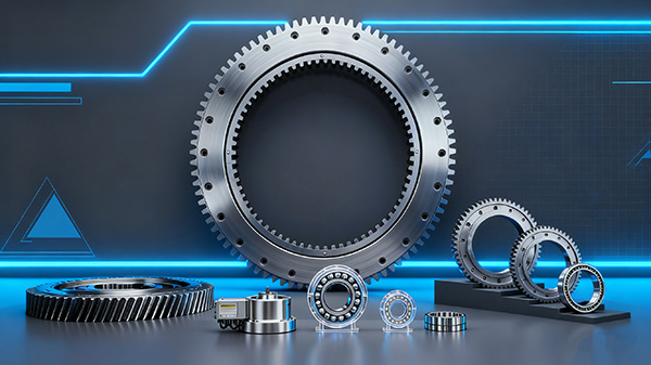
The gear configuration is an important part of slewing bearing design. Depending on the equipment layout and drive system, a slewing bearing may use an external gear, an internal gear, or no integral gear at all.
At first glance, the difference appears simple: external gears have teeth on the outside, internal gears have teeth on the inside, and gearless bearings have no teeth. In actual equipment design, however, the choice affects drive arrangement, installation space, gear protection, lubrication, maintenance access, and integration with the mating pinion.
For engineers and purchasing teams, selecting a suitable configuration therefore requires more than comparing bearing dimensions. The gear design must work together with the bearing structure, drive system, loads, operating conditions, and surrounding equipment.
This guide explains the differences between internal gear, external gear, and gearless slewing bearings, the key gear specifications to check, and the information needed when selecting or ordering a slewing bearing.
Understanding the Three Slewing Bearing Gear Configurations
A slewing bearing supports rotational movement between two machine structures. In many applications, the bearing also works with a drive system that provides the torque required for rotation.
When the gear is integrated directly into one of the bearing rings, the result is generally an internal-gear or external-gear slewing bearing. If the bearing rings are manufactured without integral gear teeth, the bearing is described as gearless.
The three configurations can be summarized as follows:
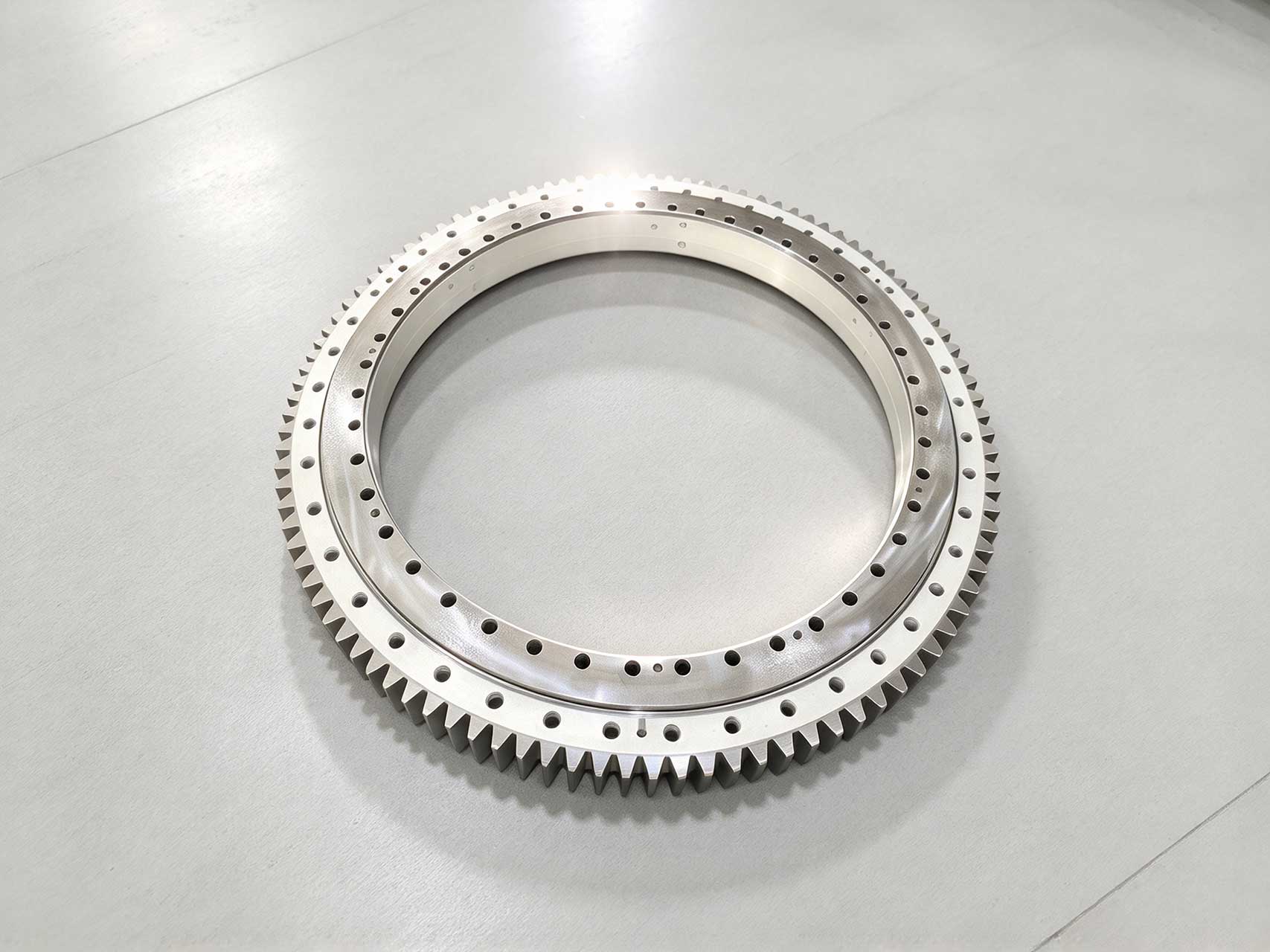
External gear: gear teeth are machined on the outside of the bearing ring.
Internal gear: gear teeth are machined on the inside of the bearing ring.
Gearless: no integral gear is machined into the bearing rings.
The appropriate configuration depends on how the equipment is designed to rotate.
For example, the available space around the bearing may determine whether a drive pinion can be positioned outside or inside the bearing. Environmental exposure may affect how the gear needs to be protected, while maintenance requirements can influence the preferred access to the gear mesh.
The gear configuration also needs to be considered together with the bearing's basic function. Depending on its internal design, a slewing bearing can support combinations of axial load, radial load, and tilting moment while allowing relative rotation between the connected structures.
For this reason, gear configuration should not be treated as an isolated feature. It is part of the complete bearing and drive-system design.
What Is an External Gear Slewing Bearing?
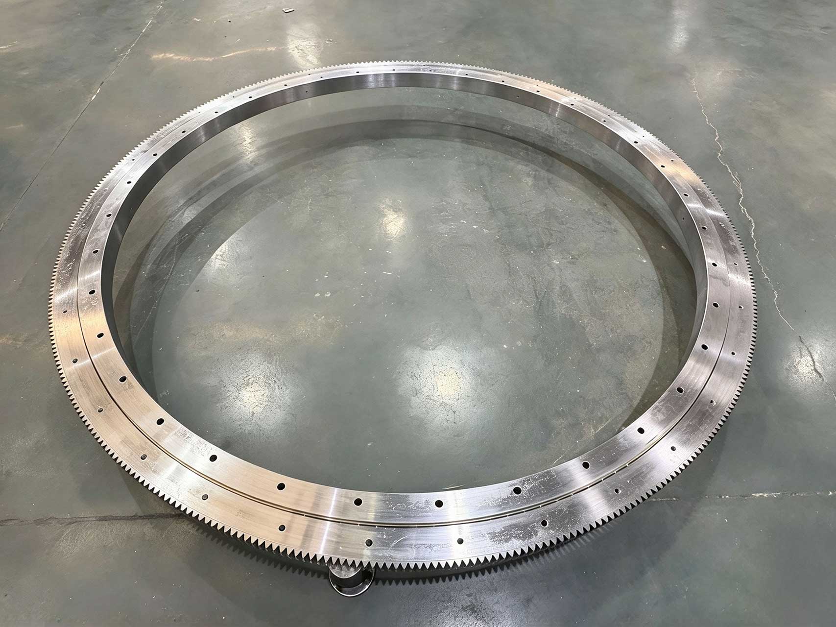
An external gear slewing bearing has gear teeth machined around the outer circumference of one of its rings. A drive pinion is positioned outside the bearing and meshes with these teeth to rotate one ring relative to the other.
This arrangement is widely used because the external gear is directly accessible from outside the bearing.
Drive Arrangement
In an external-gear design, the pinion and drive unit are positioned outside the main bearing diameter.
This can simplify the mechanical arrangement when sufficient radial space is available around the bearing.
The external location can also make it easier to visually inspect the gear mesh, check tooth condition, apply lubrication, or access the drive pinion during maintenance.
However, these advantages depend on the actual machine structure. Guards, housings, frames, and other components may still restrict access.
Installation Space
Because the gear teeth extend around the outside of the bearing, an external-gear configuration requires adequate radial space for both the gear and mating pinion.
This must be considered during equipment design.
When replacing an existing bearing, engineers should check not only the outer diameter of the ring but also the gear dimensions and the position of the drive pinion.
A bearing with similar ring dimensions but different external gear geometry may not be compatible with the existing drive system.
Environmental Exposure
The external position of the gear can make it more exposed to dust, moisture, debris, and other contaminants, depending on the equipment.
This does not mean an external gear is unsuitable for demanding environments. It means that gear protection, lubrication, sealing around the equipment, and maintenance practices should be considered as part of the complete system.
Protective covers or guards may be used where necessary.
External gear slewing bearings can therefore be a practical choice when the equipment provides sufficient outside space and the drive arrangement benefits from an externally positioned pinion.
What Is an Internal Gear Slewing Bearing?
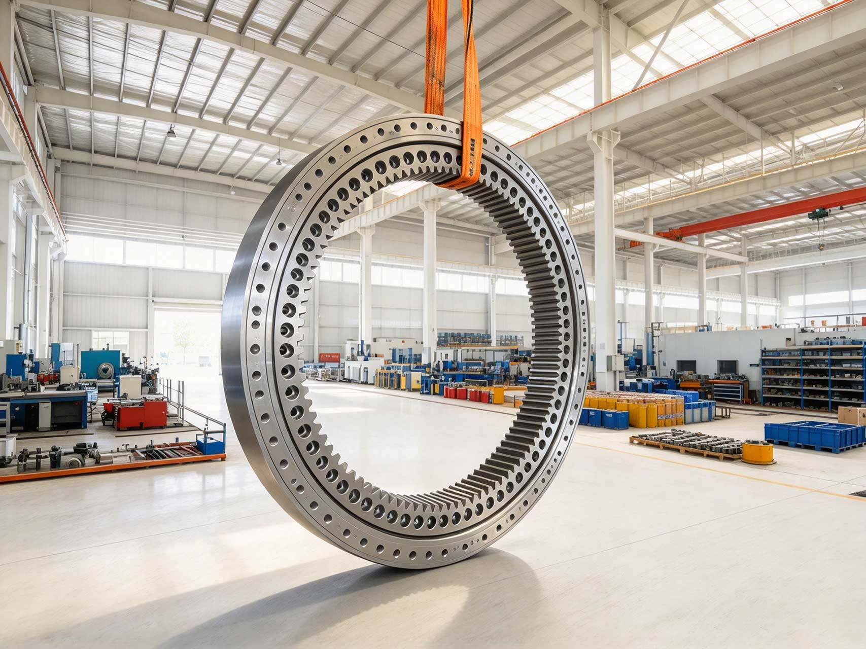
An internal gear slewing bearing has gear teeth machined on the inner circumference of one of the bearing rings. The mating pinion operates inside the bearing diameter.
The main difference from an external-gear design is therefore not simply the direction of the teeth. The location of the drive system changes as well.
Compact External Arrangement
Because the gear is located inside the bearing, an internal-gear design can reduce the radial space required by the drive system outside the bearing.
This can be useful when surrounding structures, covers, or other machine components limit the available external space.
However, internal gear does not automatically mean that the entire machine will always be smaller. Adequate space is still required inside the bearing for the pinion, drive components, inspection, and maintenance.
The complete equipment layout must therefore be evaluated.
Gear Protection
The internal position can provide some protection from direct external exposure because the teeth face toward the center of the bearing.
This can be beneficial in certain equipment arrangements, but an internal gear should not be considered automatically protected from contamination.
Dust, moisture, worn lubricant, and other contaminants can still reach the gear mesh depending on the machine design and operating environment.
Appropriate lubrication and protection remain necessary.
Inspection and Maintenance Access
Compared with an exposed external gear, access to an internal gear can be more dependent on the equipment structure.
Engineers should consider whether the pinion, gear teeth, lubrication points, and inspection areas remain accessible after the bearing is installed.
This is particularly important in equipment where surrounding structures make internal access difficult.
Internal gear slewing bearings can be appropriate when the drive system can be integrated within the bearing diameter and the equipment benefits from keeping the external circumference relatively compact.
What Is a Gearless Slewing Bearing?
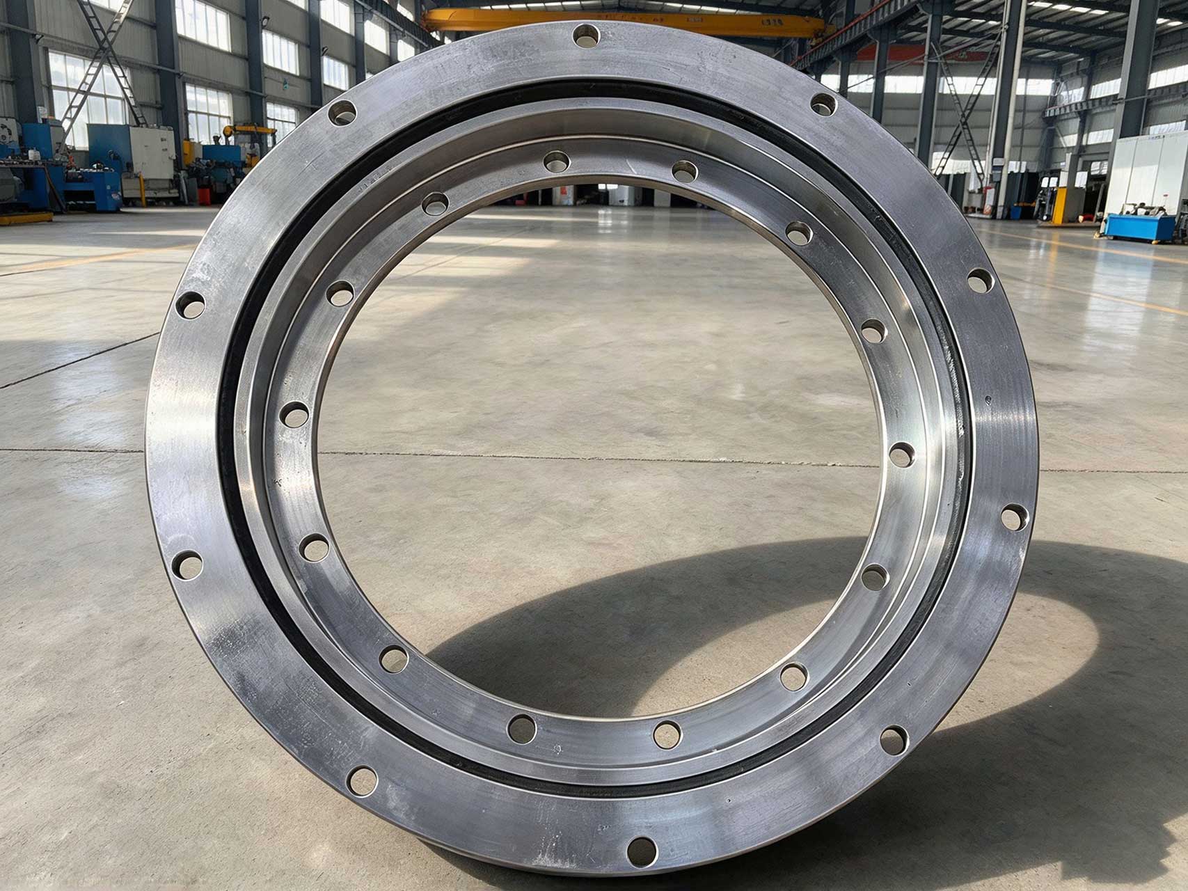
A gearless slewing bearing does not have integral gear teeth machined into either bearing ring.
The bearing still performs its primary functions of supporting loads and allowing relative rotation, but rotational torque must be provided through another drive arrangement if powered rotation is required.
This distinction is important because gearless does not mean incomplete or lower quality. It simply describes a different mechanical configuration.
Why Use a Gearless Design?
Not every rotating system needs an integral gear on the slewing bearing.
Some equipment may use a separate gear system, friction drive, hydraulic arrangement, or another mechanism to create rotational movement. Other applications may require the bearing mainly to support and guide rotation rather than to form part of a geared transmission.
Removing the integral gear can also be appropriate when the equipment designer already has a separate drive solution.
Equipment Integration
With a gearless bearing, the equipment manufacturer has greater responsibility for determining how torque will be transmitted to the rotating structure.
The drive solution must still satisfy the required torque, speed, positioning, and operating conditions.
Therefore, choosing a gearless bearing should not be viewed simply as removing one specification from the bearing. It changes the way the bearing integrates with the overall drive system.
When replacing an existing geared bearing with a gearless design—or the reverse—the surrounding equipment normally requires additional engineering evaluation. These configurations should not be considered directly interchangeable based only on OD, ID, and height.
Internal Gear vs. External Gear vs. Gearless: Key Differences
There is no single gear configuration that is suitable for every slewing bearing application.
The practical differences become clearer when the three designs are compared according to equipment integration rather than simply according to the location of the teeth.
| Factor | External Gear | Internal Gear | Gearless |
|---|
| Gear Position | Outside circumference | Inside circumference | No integral gear |
|---|
| Typical Pinion Position | Outside bearing | Inside bearing | Depends on separate drive system |
|---|
| External Radial Space | Additional space may be required for gear and pinion | Can reduce external drive-space requirements | Depends on drive arrangement |
|---|
| Gear Exposure | Can be more directly exposed to the environment | Can receive some protection from its internal position | No integral bearing gear to protect |
|---|
| Inspection Access | Often relatively accessible, depending on machine structure | Depends more strongly on internal equipment access | Depends on separate drive system |
|---|
| Lubrication | Gear mesh requires appropriate lubrication | Gear mesh requires appropriate lubrication | Determined by separate drive system |
|---|
| Drive Integration | Suitable for an externally positioned pinion | Suitable for an internally positioned pinion | Requires another method of transmitting rotation |
|---|
| Replacement Check | Gear geometry and pinion position must match | Gear geometry and internal drive arrangement must match | Complete drive arrangement must be evaluated |
|---|
These differences demonstrate why the decision cannot be reduced to a simple statement such as "internal gear is better protected" or "external gear is easier to maintain."
For example, an external gear may provide excellent maintenance access on one machine but become difficult to reach after protective guards are installed on another. An internal gear may reduce external space requirements but create access restrictions inside a compact machine.
The correct choice depends on the entire equipment arrangement.
For replacement projects, this also means that an internal-gear bearing should not normally be replaced by an external-gear version simply because the main bearing dimensions are similar. The drive position, mounting structure, gear geometry, and surrounding components would all need to be evaluated.
Key Gear Specifications to Check in a Slewing Bearing
Selecting between internal, external, and gearless configurations is only the first step.
For a geared slewing bearing, the gear must also be compatible with the mating pinion and drive system. Several specifications are particularly important.
Gear Module
Module is a basic metric parameter used to describe gear tooth size.
The mating pinion and slewing bearing gear must use compatible tooth geometry. A pinion with an incompatible module will not mesh correctly with the bearing gear.
Module therefore needs to be confirmed when designing a new drive system and when replacing an existing geared bearing.
Number of Teeth
The number of teeth is another fundamental specification.
Together with module and other gear geometry, tooth count is related to the pitch diameter and influences the transmission relationship between the drive pinion and slewing bearing.
For replacement projects, a difference in tooth count should not be treated as a minor variation. It can affect the drive ratio, rotational behavior, and compatibility with the existing pinion.
Pitch Diameter
Pitch diameter is a theoretical diameter associated with the meshing action of the gear.
It is different from the outside diameter of the bearing and should not be confused with the physical diameter measured across the tips of the gear teeth.
Understanding this distinction is especially important when reviewing a slewing bearing drawing, because several different diameters may be shown in the same gear section. Pressure Angle
Pressure angle is another parameter that affects gear tooth geometry and meshing.
The bearing gear and mating pinion must be designed as a compatible gear pair. Module alone is therefore not sufficient to confirm that two gears can work together.
When replacing a slewing bearing, the pressure angle and other relevant tooth specifications should be verified from the original drawing or technical documentation whenever available.
Gear Accuracy
Gear manufacturing accuracy can affect tooth contact, transmission smoothness, noise, wear, and positioning behavior.
The required accuracy depends on the application.
Equipment requiring controlled positioning may have different requirements from heavy machinery operating at low speed with different precision demands.
For this reason, the necessary gear accuracy should be specified according to the equipment requirements rather than automatically selecting the tightest available tolerance.
Backlash
Backlash is the clearance between mating gear teeth in the assembled gear pair.
Appropriate backlash is necessary to accommodate manufacturing tolerances, installation conditions, lubrication, temperature effects, and operating requirements.
Too little backlash can result in poor meshing, increased friction, heat, or tooth interference. Excessive backlash can affect positioning and create additional movement between the mating gears.
Importantly, gear backlash should not be confused with slewing bearing clearance. Bearing clearance concerns relative movement within the bearing's rolling contact system, while gear backlash concerns the meshing relationship between the bearing gear and drive pinion. Pinion Compatibility
The bearing gear and drive pinion should always be considered as a working pair.
Module, pressure angle, tooth geometry, center distance, alignment, gear accuracy, lubrication, and backlash can all influence meshing performance.
For replacement projects, providing information about the existing pinion can therefore be just as important as providing the slewing bearing dimensions.
How to Choose the Right Slewing Bearing Gear Configuration
Choosing between an internal gear, external gear, and gearless bearing should begin with the equipment requirements rather than with a preferred bearing style.
Several factors should be evaluated together.
Available Installation Space
Review the space both inside and outside the bearing.
An external gear requires space around the outside circumference for the teeth and pinion. An internal gear moves the gear mesh inward but requires sufficient internal space for the pinion and associated drive components.
A gearless design depends entirely on the space requirements of the separate drive solution.
Drive and Pinion Arrangement
Determine where the motor, gearbox, hydraulic motor, or other drive source can be installed.
The position of the drive unit can strongly influence whether an internal or external gear is more practical.
For existing machinery, the pinion location may already determine the required gear configuration.
Required Torque and Gear Ratio
The drive system must provide sufficient torque to rotate the equipment under the expected operating conditions.
Gear geometry and the relationship between the pinion and bearing gear also influence the transmission ratio.
Normal operating torque should be considered together with starting conditions and other demanding load cases relevant to the equipment.
Load Conditions
Gear configuration should not replace proper bearing load evaluation.
The bearing itself may need to support axial load, radial load, and tilting moment simultaneously. These loads influence bearing structure and size, while the gear transmits the torque required for rotation.
Both functions must be considered during selection.
Rotation Speed and Duty Cycle
Some slewing systems move only occasionally, while others perform frequent start-stop movements, repeated positioning cycles, or more continuous rotation.
Speed and duty cycle can influence gear lubrication, heat generation, wear, and drive-system requirements.
They should therefore be provided during bearing and gear selection.
Operating Environment
Outdoor equipment, dusty industrial machinery, marine environments, high or low temperatures, and other demanding conditions may require additional consideration of gear protection, lubrication, seals, materials, or surface treatment.
The location of the gear can influence its exposure, but gear configuration alone does not provide complete environmental protection.
Lubrication and Maintenance Access
The gear mesh requires appropriate lubrication and periodic inspection according to the equipment's maintenance requirements.
Before choosing the configuration, consider whether maintenance personnel can access the gear and pinion after the machine is fully assembled.
A theoretically convenient arrangement may become difficult to maintain if surrounding equipment blocks access.
Positioning and Accuracy Requirements
Equipment requiring accurate positioning may place tighter requirements on gear accuracy, backlash, bearing clearance or preload, structural rigidity, and drive control.
These parameters should be evaluated as a system.
Therefore, the selection process is not simply:
Internal gear vs. external gear vs. gearless.
A more useful approach is:
Installation space → drive arrangement → torque → loads → speed and duty cycle → environment → maintenance → accuracy requirements.
Following this sequence helps identify a gear configuration that fits the complete machine rather than selecting one feature in isolation.
What Information to Provide When Ordering a Geared Slewing Bearing
Providing complete technical information can make slewing bearing selection and quotation more efficient and reduce the risk of dimensional or drive-system incompatibility.
For a new design or replacement project, useful information can include:
Existing bearing drawing, if available
Equipment assembly drawing
Required internal, external, or gearless configuration
Outer diameter
Inner diameter
Overall height
Mounting hole dimensions and bolt circle diameters
Gear module
Number of teeth
Pressure angle, where applicable
Gear accuracy requirements
Existing or proposed drive pinion information
Axial load
Radial load
Maximum tilting moment
Required output torque
Rotation speed
Duty cycle
Accuracy or positioning requirements
Lubrication requirements
Operating temperature
Dust, moisture, corrosion, or other environmental conditions
For replacement bearings, the original drawing is particularly useful because it can provide dimensional, mounting, and gear information that may be difficult to determine accurately from a worn bearing.
However, the drawing should still be considered together with the current operating conditions. If the equipment has been modified, its loads, operating frequency, drive system, or environment may differ from the original design conditions.
When standard specifications do not match the equipment requirements, customized bearings can be developed around the required dimensions, mounting interface, bearing structure, gear configuration, and operating conditions.
For customers who are uncertain whether an internal gear, external gear, or gearless configuration is appropriate, providing the equipment drawing, drive arrangement, load data, and operating requirements allows the application to be reviewed more systematically.
Why Choose LTZC for Slewing Bearing Solutions?
Selecting a slewing bearing involves more than choosing between an internal gear, external gear, and gearless design. The bearing structure, gear specifications, mounting dimensions, load conditions, and operating requirements must work together as a complete system.
LTZC supports slewing bearing projects from application evaluation and product selection to specification review and customized design. For non-standard applications, bearing dimensions, mounting interfaces, internal structures, and gear configurations can be developed according to the equipment requirements.
Depending on the application, customized solutions can include four-point contact ball, double-row ball, crossed roller slewing bearings, and three-row roller slewing bearing structures, together with internal gear, external gear, gearless, and other required configurations.
For replacement projects, customers can provide an existing bearing drawing, equipment drawing, gear specifications, or available dimensional information for technical review. For new equipment, load data, drive arrangement, mounting requirements, rotation speed, duty cycle, and operating environment can be considered together during bearing selection.
This application-based approach helps ensure that the selected slewing bearing not only matches the required dimensions but also works with the equipment's load and drive requirements.
Looking for a standard or customized slewing bearing? Send LTZC your drawing and application requirements for technical review.
 WhatsApp
 jessica.chai@ltzzc.com
 0086-379-69950051