WhatsApp
 jessica.chai@ltzzc.com
 0086-379-69950051

How to Read a Slewing Bearing Drawing: Key Dimensions, Tolerances, and Specifications
Technical drawings for slewing bearings contain much more than the overall size of the bearing. They define the mounting interface, ring dimensions, hole pattern, gear geometry, clearance, tolerances, and other technical information required to determine whether a bearing can be installed and operate correctly in a particular machine.
For engineers and purchasing teams, understanding these specifications is especially important when selecting a new bearing or replacing an existing one. Two slewing bearings may appear similar and even share the same outer and inner diameters, but differences in mounting holes, gear geometry, internal structure, clearance, or load requirements can make them unsuitable substitutes.
This guide explains how to read the main information on a slewing bearing drawing and which specifications should be checked before selection, replacement, or requesting a quotation.
Why Slewing Bearing Drawings Matter in Selection and Replacement
A technical drawing provides the dimensional interface between the slewing bearing and the equipment around it.
It allows engineers to determine whether the bearing fits the available installation space, whether its mounting holes correspond with the supporting structure, and whether the gear can work with the existing drive system.
However, dimensional compatibility is only part of the selection process.
A slewing bearing must normally support a combination of axial load, radial load, and tilting moment. Its suitability therefore also depends on internal structure, material, raceway design, precision, operating speed, duty cycle, lubrication, and other working conditions.
This distinction becomes particularly important in replacement projects.
An existing drawing can provide valuable dimensional information, but finding a bearing with similar dimensions does not automatically mean that the new bearing is technically interchangeable with the original one.
A proper replacement review should consider two questions:
Will the bearing physically fit the equipment?
Can the bearing meet the actual operating requirements?
Both must be addressed before a replacement bearing is confirmed.
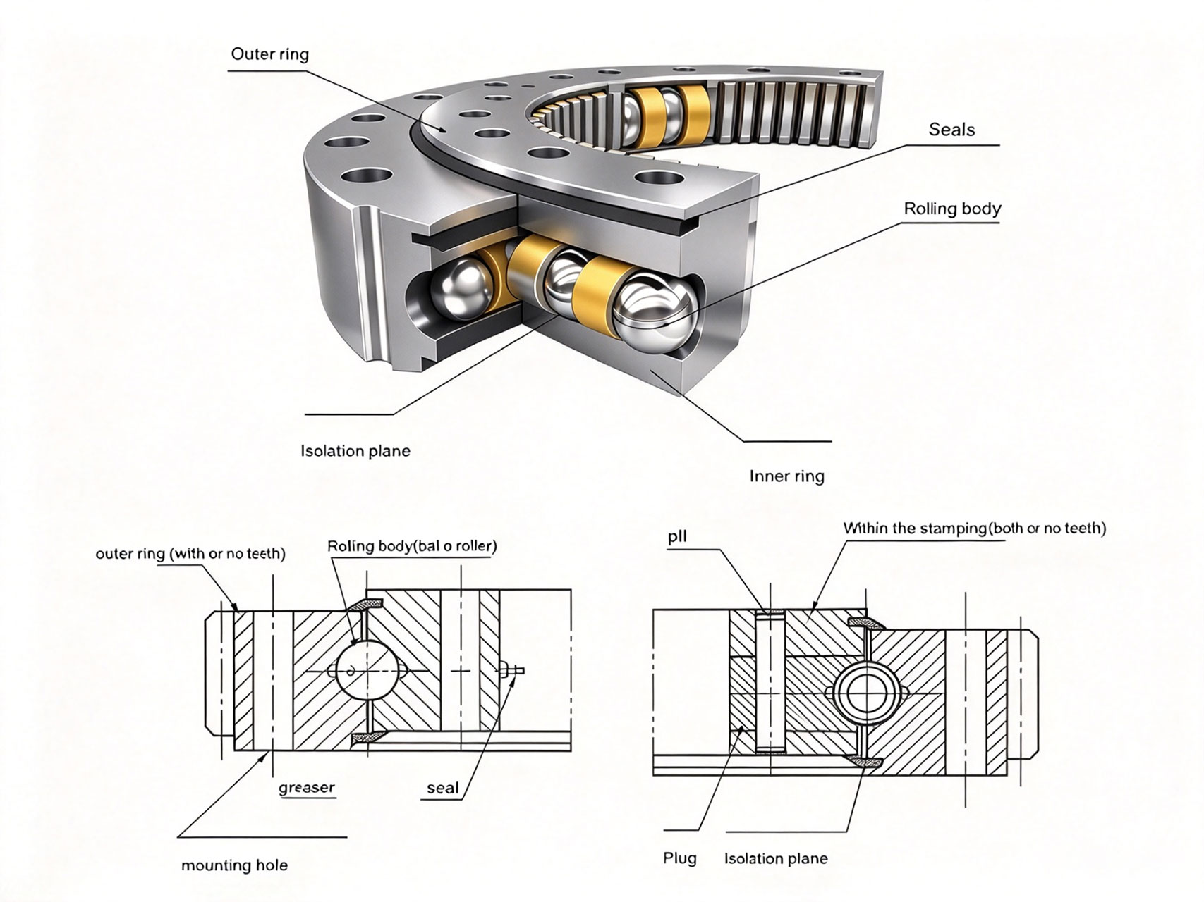
Start with the Basic Slewing Bearing Dimensions
The first step when reviewing a slewing bearing drawing is to identify its main envelope dimensions. These determine how much installation space the bearing requires and how it interfaces with adjacent structures.
Outer Diameter
The outer diameter, commonly abbreviated as OD, defines the maximum outside dimension of the bearing rings.
It is important for checking available installation space and possible interference with nearby machine components.
On geared bearings, care should be taken when interpreting this dimension. Depending on the drawing, the maximum outside diameter may include an external gear, while another dimension may identify the ring body itself.
Always follow the dimension references shown on the specific drawing rather than assuming that every OD is defined in the same way.
Inner Diameter
The inner diameter, or ID, defines the central opening through the bearing.
This space may be required for hydraulic lines, electrical cables, drive components, structural members, or other machine systems.
In replacement applications, even a relatively small difference in ID can interfere with existing components. It should therefore be checked against the equipment assembly rather than considered only as a bearing dimension.
Overall Height
Overall height describes the total axial dimension of the bearing.
This specification affects the vertical position of the connected machine structures and may also influence alignment with the drive pinion or surrounding components.
When comparing replacement bearings, checking only OD and ID is not sufficient. Overall height must also match the available mounting envelope or be evaluated to determine whether equipment modifications are required.
Ring Dimensions and Mounting Envelope
Detailed drawings may include additional dimensions for the inner and outer rings, shoulders, steps, flanges, locating surfaces, seals, and gear positions.
Together, these dimensions define the complete mounting envelope.
For a new machine design, engineers can often adapt the surrounding structure to the selected bearing. In a replacement project, however, the existing machine usually determines the allowable dimensions. This makes accurate drawing review especially important.
How to Read Mounting Holes and Bolt Circle Dimensions
Once the main dimensions have been confirmed, the next step is to examine the mounting interface.
Slewing bearings are normally attached to the supporting structures through mounting holes distributed around the inner and outer rings. These holes transfer operating loads between the bearing and the machine structure.
Bolt Circle Diameter
Bolt Circle Diameter, often shown as BCD or PCD, describes the diameter of the imaginary circle passing through the centers of the mounting holes.
The inner and outer rings may have different bolt circle diameters.
When evaluating a replacement bearing, both must correspond with the mating structure unless the equipment itself will be modified.
A bearing with the correct OD and ID but an incorrect bolt circle cannot normally be installed directly onto the existing mounting structure.
Number and Diameter of Mounting Holes
The drawing should also specify the number of holes and their diameters.
These values should not be changed casually. The mounting bolts form part of the load-transfer system, and bolt quantity, size, grade, preload, and arrangement can affect the integrity of the complete slewing assembly.
For replacement projects, verify the mounting holes against both the existing bearing and the equipment drawing whenever possible.
Through Holes and Threaded Holes
Mounting holes may be plain through holes or threaded holes, depending on the bearing and equipment design.
This difference is important because it affects bolt installation and the design of the mating structure.
A drawing may use standard mechanical drawing symbols or notes to identify thread specifications, counterbores, countersinks, or other hole features. These details should be reviewed carefully rather than treating all holes of the same diameter as equivalent.
Hole Position and Spacing
Mounting holes may be equally spaced around the circumference, but special patterns are also possible.
Some designs can include locating features, grease holes, lifting holes, plugged holes, or other functional details that interrupt an otherwise regular pattern.
For this reason, replacement evaluation should consider the complete hole arrangement, not only the total number of mounting holes.
Understanding Slewing Bearing Gear Specifications
Many slewing bearings incorporate a gear into one of the rings so that torque can be transmitted from a drive pinion to the rotating structure.
The gear section of the drawing is therefore essential when the bearing is part of an existing drive system.
Internal Gear, External Gear, and Gearless Designs
An external-gear slewing bearing has gear teeth on the outside of one ring, while an internal-gear bearing has teeth on the inside.
A gearless slewing bearing has no integral gear and requires another method of driving the rotating structure.
The appropriate configuration depends on equipment layout, available installation space, drive arrangement, protection requirements, and other design considerations.
When replacing a geared bearing, the gear position must correspond with the existing drive arrangement.
Gear Module
Module is a fundamental metric gear parameter related to tooth size.
The bearing gear and mating pinion must have compatible gear geometry. A difference in module means the tooth geometry will not mesh correctly even if other bearing dimensions appear similar.
For this reason, module should always be verified when reviewing a replacement drawing.
Number of Teeth
The number of teeth is another critical specification.
Together with the gear geometry, it affects the pitch diameter and transmission relationship between the slewing bearing and drive pinion.
Changing the number of teeth can affect the drive ratio and equipment motion, so it should not be treated as a minor dimensional difference.
Pitch Diameter
Pitch diameter is a theoretical gear dimension associated with the meshing action between gears.
It should not be confused with the physical outside diameter of the bearing or the tip diameter of the gear teeth.
When checking compatibility with an existing pinion, engineers should review the complete gear data rather than comparing only the visible outside diameter.
Gear Accuracy and Backlash Considerations
Correct gear meshing depends on more than module and tooth count.
Gear accuracy, center distance, tooth geometry, runout, installation alignment, and operating conditions can all influence contact between the slewing bearing gear and the mating pinion.
Backlash must also be appropriate for the specific gear pair and operating condition. It should be checked during installation according to the relevant drawing and technical requirements rather than determined from a generic value.
If a replacement bearing uses a different gear specification, the drive system should be reviewed before installation.
How to Interpret Clearance, Tolerances, and Running Accuracy
After the primary dimensions and mounting interface have been checked, attention should turn to the specifications that control movement and precision.
These parameters can be particularly important in equipment requiring stable positioning, controlled rotation, or high structural rigidity.
Axial and Radial Clearance
Slewing bearing clearance describes the relative movement available between the bearing rings and rolling elements.
Axial clearance relates to movement along the bearing axis, while radial clearance relates to movement in the radial direction.
The appropriate values depend on bearing structure and operating requirements. Smaller clearance should not automatically be considered better because insufficient clearance can increase internal resistance, friction, and sensitivity to operating conditions.
For this reason, clearance specifications should be interpreted in relation to the application rather than as isolated dimensions.
When reviewing a replacement drawing, the specified clearance should be compared with the requirements of the original equipment and actual operating conditions.
Dimensional Tolerances
A drawing normally includes tolerances for critical dimensions.
A nominal dimension alone does not fully define the manufactured component. The permitted variation around that dimension determines whether the bearing can be assembled correctly with the mating structure.
Tolerances can be particularly important for locating surfaces, mounting interfaces, ring dimensions, and other features that influence fit and alignment.
The required tolerance level depends on the application and should follow the technical specification associated with the bearing.
Axial and Radial Runout
Runout describes variation observed as a component rotates relative to a reference surface or axis.
In applications requiring accurate rotation, excessive runout can affect positioning and the behavior of connected components.
The acceptable level depends on bearing design and machine requirements. Precision equipment may require tighter control than general heavy-duty rotating machinery.
Rotational Accuracy
Rotational accuracy should be considered when the machine requires controlled positioning or repeatable motion.
It can be influenced by bearing geometry, raceway accuracy, clearance or preload, manufacturing precision, mounting accuracy, and the rigidity of the surrounding structure.
A bearing drawing should therefore be reviewed together with the machine's actual accuracy requirements.
Check Load Capacity and Operating Requirements
One of the most important principles in reading a slewing bearing drawing is understanding what the drawing cannot tell you by dimensions alone.
Dimensional compatibility does not automatically mean application compatibility.
A replacement bearing may fit perfectly into the mounting space and still be unsuitable for the loads or operating conditions.
Axial Load
Axial load acts parallel to the bearing's rotational axis.
In many slewing applications, it represents a significant portion of the operating load. However, it rarely acts completely independently.
Radial Load
Radial load acts perpendicular to the rotational axis.
Its magnitude and relationship with the other load components should be considered during bearing selection.
Tilting Moment
Tilting moment is particularly important for slewing bearings because the supported structure often creates a load at a distance from the bearing center.
Cranes, platforms, material-handling equipment, and other rotating machinery can generate substantial overturning moments.
The bearing must therefore be evaluated for the combined load condition rather than selected according to a single axial or radial capacity figure.
Rotation Speed and Duty Cycle
Slewing bearings are used under widely different operating patterns.
Some rotate only occasionally. Others perform frequent indexing or start-stop movements, while certain applications require more continuous rotation.
Rotational speed and duty cycle affect lubrication, heat generation, friction, and long-term operating conditions. They should therefore be included when reviewing the suitability of a bearing.
Accuracy and Rigidity Requirements
Two machines with similar load levels may still require different bearing configurations if one requires much higher positioning accuracy or rigidity.
The selected bearing structure, clearance or preload, precision level, and supporting structure must work together to meet the machine's functional requirements.
For this reason, a drawing should be treated as one part of the technical specification rather than the sole basis for selection.
What to Check When Replacing an Existing Slewing Bearing
Replacement projects often begin with incomplete information.
The original bearing may have been installed many years ago. The original drawing may be unavailable, the identification may be difficult to trace, or the machine may have been modified during its service life.
A systematic review helps reduce the risk of ordering an incompatible replacement.
Start with the available documentation. An original bearing drawing is generally the most useful source because it can provide dimensions, mounting details, gear data, and other specifications.
Equipment assembly drawings can provide additional information about the surrounding structure and installation space.
If complete drawings are unavailable, measurements from the existing bearing may help establish key dimensions. These can include OD, ID, overall height, bolt circle diameters, hole sizes and quantities, and gear information.
However, measuring a used bearing has limitations. Wear, corrosion, damage, previous modifications, and measurement conditions can affect the results.
The next step is to confirm the bearing structure. A four-point contact ball bearing, cross roller slewing bearing, double-row ball bearing, and three-row roller bearing may have different internal characteristics even when their external dimensions are similar.
Gear specifications should then be checked against the existing drive system, including gear position, module, tooth count, and other relevant geometry.
The condition of the mounting surfaces, bolts, lubrication system, and gear mesh should also be reviewed. Proper slewing bearing installation and maintenance can affect operating performance and service life, while installation-related problems can sometimes produce symptoms that appear to originate from the bearing itself.
Finally, the original and current operating conditions should be reviewed. If the equipment has been modified to carry heavier loads, operate more frequently, or work in a different environment, simply reproducing the original dimensions may not provide the most appropriate solution.
For a reliable replacement review, consider the complete chain:
Dimensions → mounting holes → gear specifications → bearing structure → clearance and precision → loads → speed and duty cycle → operating environment.
This approach is more reliable than selecting a replacement based on a model number or a few primary dimensions alone.
What Information to Send LTZC for Drawing Review and Customization
Providing complete technical information at the beginning of an inquiry can make bearing selection and drawing review more efficient.
Depending on the project, useful information can include:
Existing slewing bearing drawing
Equipment assembly drawing
Outer diameter and inner diameter
Overall bearing height
Inner and outer ring mounting dimensions
Bolt circle diameters
Mounting hole quantity and size
Internal, external, or gearless configuration
Gear module
Number of teeth
Axial load
Radial load
Maximum tilting moment
Rotational speed
Duty cycle
Accuracy and rigidity requirements
Operating temperature
Lubrication requirements
Environmental conditions
Information about the existing bearing and its service history
If only partial information is available, provide as much verified data as possible rather than estimating unknown technical parameters.
For projects where standard dimensions or specifications cannot meet the equipment requirements, customized bearings can be developed around the actual mounting interface and operating conditions.
LTZC provides application analysis, load evaluation, product selection, specification support, and customized design services for slewing bearing projects. For customized applications, engineering support can also include bearing drawings, load analysis, and service-life calculations.
For non-standard bearings, LTZC supports different slewing bearing structures, including four-point contact ball, double-row ball, crossed roller, and three-row roller designs, as well as internal-gear, external-gear, gearless, and split configurations.
Quality inspection is another important part of customized production. LTZC states that its non-standard bearing inspection covers more than 20 parameters, including radial clearance, rotational accuracy, and tooth profile accuracy.
When an existing bearing needs to be replaced, sending the original drawing together with actual operating data allows the technical team to evaluate both dimensional compatibility and application requirements. For new equipment, drawings and operating conditions can be reviewed together to determine an appropriate bearing configuration.
Need help reviewing a slewing bearing drawing?
Send LTZC your existing bearing drawing, equipment dimensions, mounting information, gear specifications, load data, and operating conditions. The engineering team can review the technical requirements and assist with bearing selection, replacement matching, or a customized slewing bearing solution.
Contact LTZC to discuss your slewing bearing drawing and technical requirements.