WhatsApp
 jessica.chai@ltzzc.com
 0086-379-69950051

Understanding Axial Load Limits in Four Point Contact Ball Slewing Bearings
Engineers often face a critical question when designing rotating equipment: can a single slewing ring handle the combined loads of my application? Specifically, how do you determine if a Four Point Contact Ball Slewing Bearing has sufficient axial load capacity for your design, and at what point do you need to consider a more complex roller-based solution? This component is often the structural linchpin in equipment ranging from cranes and excavators to wind turbines and robotic arms, making the right choice essential for safety and performance.
As an engineer with over a decade of experience in slewing bearing applications, I've seen firsthand how misinterpreting load specifications can lead to premature failure. The unique geometry of a four-point contact bearing, which allows it to handle axial, radial, and tilting moment loads simultaneously, is its greatest strength. However, it also has defined operational boundaries. This guide provides direct answers to common questions about axial load, helping you specify the right bearing for long-term reliability. We will explore the key factors that define its capacity, the clear indicators for when a roller bearing is necessary, and how to properly prepare your technical specifications for an accurate quotation.
Key Factors Influencing Axial Load Capacity
The maximum axial load a slewing bearing can withstand is not a single, static number. It's a calculated value derived from several interconnected design and material factors. Understanding these elements is the first step in proper bearing selection. Our ISO 9001:2015 certified manufacturing process ensures tight control over each of these variables for consistent performance.
Raceway Geometry: The defining feature of this bearing type is its "Gothic arch" raceway. This specific curvature creates four contact points between a single ball and the inner and outer rings. The precise angle and conformity of this arch directly determine how axial loads are distributed. A well-designed raceway ensures loads are transferred efficiently, maximizing capacity and minimizing contact stress.
Ball Diameter and Quantity: Larger steel balls can support higher loads. Similarly, increasing the number of balls within the raceway distributes the total load across more rolling elements, thereby increasing the bearing's overall static and dynamic capacity. However, there is a trade-off between the number of balls and their diameter within a given pitch circle.
Material Selection and Hardness: The material's ability to resist deformation under load is fundamental. We typically use high-quality bearing steel like GCr15 (or SUJ2 for high-precision applications), which offers excellent hardness and wear resistance after heat treatment. For applications requiring corrosion resistance, such as those found in Marine & Defense Slewing Bearings, materials like AISI 440C are a superior choice. The depth and uniformity of the raceway hardness are also critical for preventing brinelling (permanent indentation) under high static axial loads.
Structural Integrity of Bearing Rings: The bearing rings themselves must be rigid enough to support the rolling elements without excessive deflection. Ring cross-section, material quality, and the fastener system (bolting) all contribute to the assembly's ability to manage high axial forces and tilting moments without distortion, which could otherwise lead to uneven load distribution and premature failure.
When to Choose a Roller Bearing Over a Ball Bearing
While a four-point contact ball bearing is a versatile solution, its point-contact nature has inherent limits. Under certain conditions involving high radial forces, significant shock loading, or the need for extreme rigidity, a roller-based design provides superior performance due to its line-contact load distribution. Knowing when to transition to a roller bearing is key to avoiding field failures and ensuring operational safety.
The fundamental difference is how the load is transferred. A ball makes point contact with the raceway, concentrating the load on a very small area. A roller makes line contact, spreading the same load over a much larger area. This drastically reduces contact stress and increases load-carrying capacity and stiffness.
Use the following table to identify operating conditions that typically demand a roller bearing solution.
| Operating Condition | Four-Point Contact Ball Bearing Suitability | Recommended Roller Bearing Alternative | Why the Alternative is Better |
|---|---|---|---|
| High Radial Load | Limited. The Gothic arch raceway is optimized for axial and moment loads. Excessive radial load can cause high stress on two of the four contact points, leading to premature wear. | Cross Roller Slewing Bearings | Cylindrical rollers are arranged at 90° to each other, allowing the bearing to handle high radial loads, axial loads, and tilting moments with a single row, providing high rigidity in a compact space. |
| Heavy Shock or Impact Loading | Poor. The concentrated stress of point contact makes the raceways susceptible to brinelling (denting) under sudden, high-impact forces. | Three Row Roller Slewing Bearings | This design uses separate rows of rollers to manage axial and radial loads independently. The line contact of the rollers distributes impact forces over a larger area, significantly improving resistance to shock. |
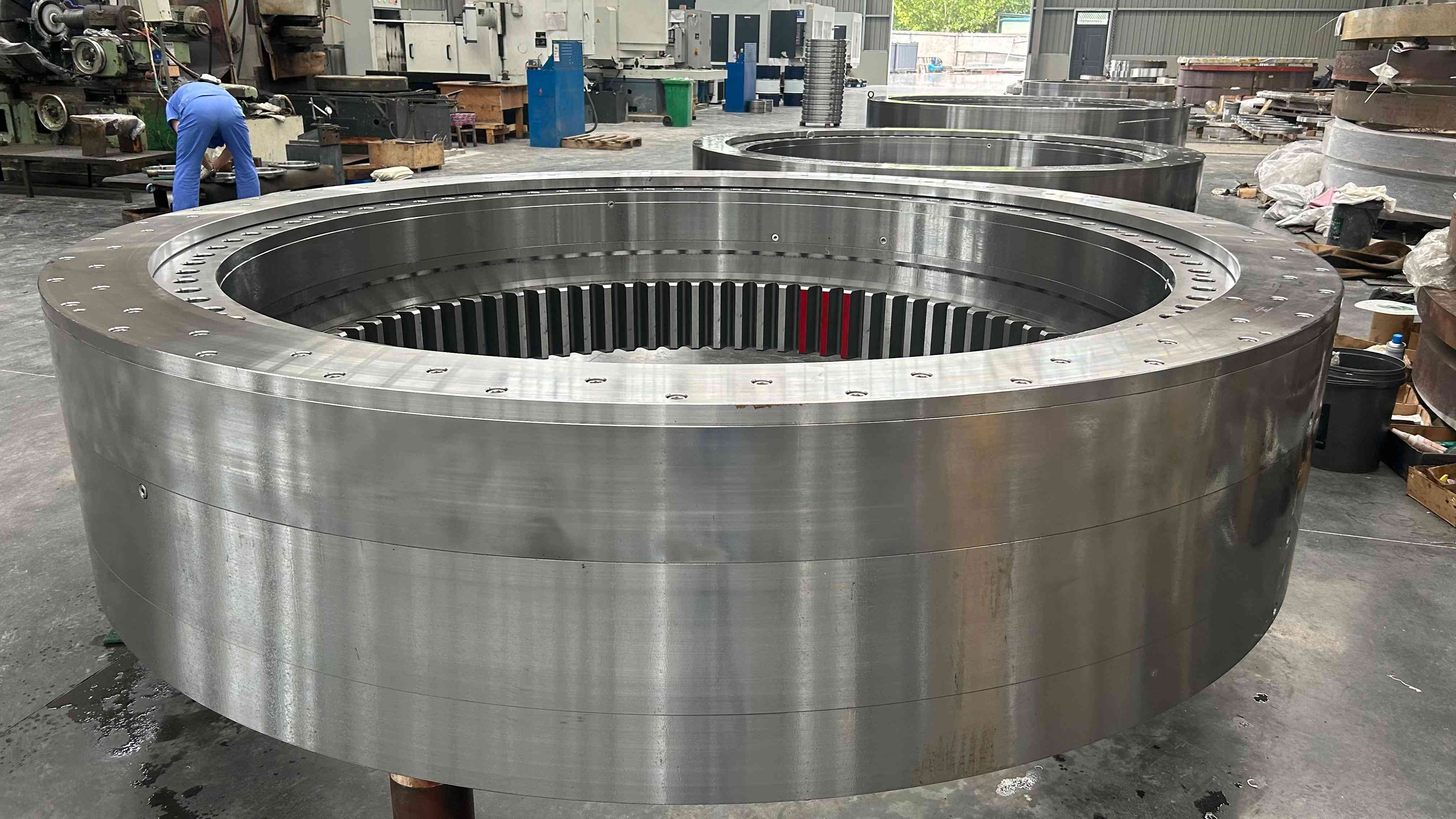
| Requirement for High Stiffness / Minimal Deflection | Moderate. Ball bearings will exhibit more deflection under load compared to roller bearings of a similar size due to the nature of point contact. | Three-Row Roller or Double-Row Ball | Line contact inherently provides greater stiffness. For the most demanding applications, like large tunnel boring machines or heavy-lift cranes, three-row roller bearings offer the highest rigidity and load capacity. This is why for a 2,000-ton lifting equipment project, our team engineered a massive 10.87-meter diameter three-row roller slewing ring. |
| Predominantly Tilting Moment Load | Good. The design handles moment loads well. However, for very large moments, the resulting internal forces can exceed the capacity of the balls. | Three-Row Roller or Ball Roller Combined Slewing Bearings | The wide spacing of the raceways in a three-row design creates a larger lever arm to counteract tilting moments effectively, providing maximum stability for equipment like large cranes and offshore platforms. |
Verifying Load Capacity for Your Application
Accurately calculating a bearing's capacity requires a full understanding of all applied loads. Simply stating the axial load is not enough. To ensure the bearing we propose meets your safety and longevity requirements, you must provide a complete load spectrum. This allows our engineers to perform the necessary calculations, including Finite Element Analysis (FEA) for complex cases.
To facilitate this process, prepare the following information before submitting a request for quotation (RFQ). This checklist ensures our engineering team has the data needed for a precise and reliable bearing selection guide and calculation.
Buyer's Checklist for a Slewing Bearing RFQ
Static and Dynamic Loads:
Axial Load (Fa): The primary vertical force on the bearing. Specify maximum and typical loads.
Radial Load (Fr): The horizontal, off-center force.
Tilting Moment (M): The load that tries to overturn the bearing, calculated as Force x Distance. This is often the most critical load in applications like cranes.
Operational Parameters:
Rotational Speed: How fast will the bearing turn (rpm)? Is the motion continuous, intermittent, or oscillating?
Duty Cycle: How many hours per day will the equipment operate? What percentage of that time is under maximum load?
Required Lifetime: Specify the desired operational life in hours or total revolutions.
Environmental Conditions:
Temperature Range: Minimum and maximum operating temperatures.
Exposure: Will the bearing be exposed to water, salt spray, dust, chemicals, or other contaminants? This dictates material choice (e.g., AISI 440C) and sealing requirements.
Mechanical Details:
Gearing: Is an internal, external, or no gear required? If so, specify the module and other gear parameters.
Mounting Structure: Provide details on the rigidity and flatness of the supporting structures. Improper mounting is a leading cause of bearing failure.
Common Failure Modes from Axial Overload
Exceeding the axial load capacity of a four-point contact ball bearing can lead to several distinct failure modes. Recognizing these helps in diagnosing issues and underscores the importance of correct initial selection. If you encounter these problems, our after-sales support team can provide fault diagnosis and technical assistance.
Common mistakes leading to overload include:
Underestimating Dynamic Forces: Failing to account for forces generated by acceleration, deceleration, and wind can lead to unexpected peak loads that exceed the bearing's static capacity.
Ignoring Tilting Moments: In many applications, the tilting moment creates the highest internal axial force on the raceways. Treating the load as purely axial is a critical error.
Incorrect Bolt Preload: Insufficient or uneven bolt tension can cause the bearing ring to distort under load, leading to load concentration on a small number of balls and subsequent failure. Our team provides detailed guidance on bearing installation to prevent this.
These mistakes can result in:
Plastic Deformation (Brinelling): When a static load is too high, it creates permanent indentations in the raceway. This damage causes noise, vibration, and high rotational friction.
Fatigue Spalling: Under excessive dynamic loads, microscopic cracks form beneath the raceway surface. Over millions of cycles, these cracks propagate to the surface, causing material to flake away (spall).
Cage Failure: Extreme overload can distort the bearing rings, pinching the ball separators (cage) and causing it to break, leading to catastrophic bearing failure.
By partnering with a knowledgeable manufacturer and providing complete load data, these failure modes are entirely preventable. Our success in producing an 8.445-meter integrated bearing for a South Korean crane client demonstrates our capability in engineering solutions for high-load, mission-critical applications.
If your project requires a unique footprint, material, or load capacity, our team is equipped to develop Customized Bearings tailored to your exact specifications. Submit your design drawings to our engineering team for a detailed review and proposal.