WhatsApp
 jessica.chai@ltzzc.com
 0086-379-69950051

How Does a Slewing Gear Ring Transmit Torque?
Engineers sizing a swing drive often ask the same question: where does the motor torque actually go once the pinion starts turning? A slewing gear ring turns pinion force into rotation of a large platform. The torque is the pinion's tangential tooth force multiplied by the pitch radius of the ring. The ring's teeth, the raceway beneath them and the mounting structure all have to carry that force without drifting out of alignment.
Our slewing ring gear parts and complete Slewing Drives follow this same principle. This article explains the load path, the parameters that change it, and the questions worth settling before you pick a bearing configuration.

The Short Answer: Torque Is a Force Acting at a Radius
A gear ring does not generate torque. It receives a tangential force at the pitch circle and passes it to the ring body, which rotates the load. Two numbers decide the result:
Tangential tooth force (Ft): set by motor and gearbox output torque divided by the pinion pitch radius.
Ring pitch radius: the larger it is, the more torque the same tooth force produces at the load.
The gear ratio between pinion and ring is simply the ring tooth count divided by the pinion tooth count. A large ring multiplies torque and cuts speed. That is why a modest pinion drive can turn a heavy upper structure slowly.
The limit of this simple view is that it covers only the tangential component. Every real mesh also produces a radial separating force and, with helical teeth, an axial force. These loads end up in the pinion bearings and the mounting structure, and they often decide whether a drive stays aligned.
Torque Path From Pinion Through Gear Teeth to the Rotating Ring
Follow the load step by step, starting at the motor:
Motor and reducer output. The reducer delivers torque to the pinion shaft.
Pinion teeth. The pinion converts shaft torque into a tangential force at its pitch circle.
Tooth mesh. A few teeth share the load at the contact line. Bending stress at the tooth root and contact stress on the flank both occur here.
Gear ring body. Force moves from the teeth into the ring section, which must resist both twisting and local deflection.
Raceway and rolling elements. The ring is part of a bearing, so it also carries axial load, radial load and tilting moment from the platform at the same time.
Bolted connection and structure. The fixed ring is bolted to the base. The reaction to the drive torque returns through the pinion housing and into that same structure.
The last step is often overlooked. The pinion mount and the bearing mount are two connections to the same frame. If the frame flexes between them, the center distance changes under load and tooth contact moves toward one edge.
Internal vs External Gear: How the Drive Layout Changes
| Item | External gear ring | Internal gear ring |
|---|---|---|
| Pinion position | Outside the ring | Inside the ring bore |
| Rotation direction | Pinion and ring turn in opposite directions | Pinion and ring turn in the same direction |
| Space | Needs clearance around the outside; the drive can be bolted on easily | More compact overall, but uses the central bore and can block cable or pipe passage |
| Access for lubrication and inspection | Teeth are open and easy to reach | Teeth are shielded, so inspection is harder |
| Tooth contact | Convex flank against convex flank | Convex flank against concave flank, which generally gives a larger contact area and more teeth in mesh |
| Typical fit | Cranes, excavators and platforms where the drive sits on the outside | Compact machines where the outside envelope is restricted |
Neither layout is simply better. Internal teeth can be attractive for compactness and mesh quality, but they make the bore unavailable and complicate service. External teeth are easier to inspect and lubricate, but they take up more space and need guarding. Choose based on where the pinion can physically sit and who will maintain it.
The ring that carries the teeth also matters. The gear can be cut on the rotating ring or on the fixed one. If the teeth are on the fixed ring, the pinion orbits with the upper structure and the motor travels with it. If they are on the rotating ring, the drive stays fixed to the base. The first case needs power and cooling routed to a moving drive, while the second needs the motor mount to react the full torque into the base.
Gear Parameters and What They Actually Change
A high value is not automatically better for any of these. Each parameter changes something else.
| Parameter | What it affects | Trade-off |
|---|---|---|
| Module (tooth size) | Bending strength of each tooth | A larger module carries more load per tooth but gives fewer teeth on a given diameter and a coarser ratio |
| Face width | Load spread along the tooth | A wider face lowers contact stress but is more sensitive to misalignment and frame deflection |
| Pressure angle and profile shift | Root strength, undercut risk and radial force | Changes that raise tooth strength can raise the separating force on the pinion bearings |
| Tooth hardness and heat treatment | Wear and pitting resistance | Harder flanks resist wear better but leave less margin for contact misalignment |
| Tooth finish (cut or ground) | Noise, contact pattern and positioning accuracy | Ground teeth cost more and take longer, so they suit precision positioning rather than every application |
| Backlash | Positioning repeatability and shock when direction reverses | Less backlash improves accuracy, but too little risks binding with thermal growth or deflection |
| Material | Strength and wear behavior | Alloy steels such as 42CrMo give higher strength for heavy loads, but the grade must match the heat treatment and section size |
The practical point: the rated tooth load of a gear ring and the load the pinion actually puts on it are different things. Peak torque during start, stop and wind or inertia loads can be well above the steady running torque. Use peak values for tooth strength and steady values for wear life.
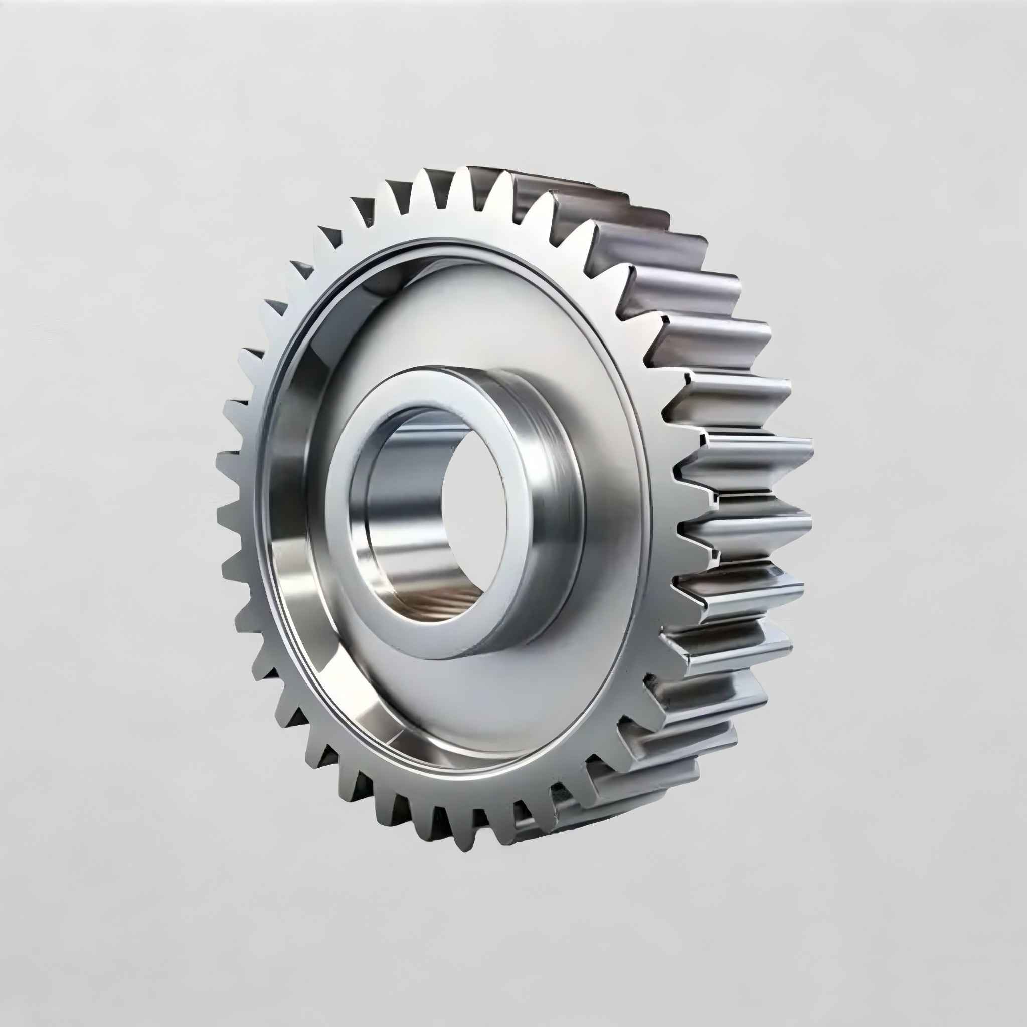
How Gear Teeth, Raceway and Structure Interact
A gear ring is rarely loaded by torque alone. Platform weight and moment loads push the ring against its rolling elements, and the same deflection that tilts the raceway also changes tooth contact. Some relationships follow from the mechanics:
Tilting moment shifts the mesh. When the ring tilts, the pinion contact moves toward one end of the tooth. This is why face width and bearing stiffness should be assessed together.
Bolted structure stiffness controls flatness. A ring bolted to a flexible frame can distort, and the teeth will not run true even if the machining was accurate.
Raceway type changes how much tilt the ring tolerates. A Three Row Roller Slewing Bearings design generally carries heavy moments with less tilt than a single row ball type, which helps keep tooth contact steady. The exact limit depends on the bearing size and load case, so request the calculated values for your application.
Heat treatment zones overlap. Hardened teeth and hardened raceways are separate features. Ask where the tooth hardening starts and stops, and where any soft zone is positioned relative to the bolt holes and the main load area.
Segmented rings add a further consideration. Very large diameters are often split into sections that are assembled at the site. Joint accuracy then governs how smoothly the pinion passes from one segment to the next. We covered the options in more detail on our Large Slewing Bearing page.
Common Misunderstandings and What to Verify
Mistakes that change the outcome
Sizing the gear for rated torque only. Peak and shock torque decide tooth strength. Without them, the selection is incomplete.
Treating the gear ring as a separate part from the bearing. The teeth, raceway and bolt pattern share one ring body, so changing one affects the others.
Choosing internal teeth only for compactness. The bore may be needed for slip rings, hydraulic lines or a center shaft.
Specifying minimum backlash without a thermal and deflection check. The mesh can bind at operating temperature or under load.
Copying a module from another machine. A tooth size that works on one frame may be wrong when stiffness or load differs.
What to ask for before ordering
Drawing with module, tooth count, pressure angle, profile shift, face width and backlash allowance
Material grade and heat treatment specification for teeth and raceway
Tooth finish method, and inspection record if teeth are ground
Where the hardened zones begin and end
Segment joint design if the ring is split
Mounting flatness and bolt requirements for the supporting structure
These documents tell you whether the teeth and bearing were designed together. They do not prove field life, which depends on lubrication, alignment and the real duty cycle. For setup, see our guidance on bearing installation.
A Worked Example and Real Delivery Cases
Illustrative example, not a customer record. Suppose a platform needs 20 kN·m of drive torque at the ring. The ring pitch diameter is 2.0 m, so the pitch radius is 1.0 m. Required tangential force at the teeth is about 20 kN. If the pinion pitch radius is 0.1 m, the pinion shaft must supply 2 kN·m. The ratio is 10:1, so the pinion runs ten times faster than the ring.
Now check it. The 20 kN tangential force is the minimum. Peak torque from starting or braking could be higher, and tooth strength must be checked against that figure. A pressure angle of 20 degrees would add a radial force of roughly 36 percent of the tangential value, about 7 kN, acting on the pinion bearings. Many designers size the pinion supports around the tangential force alone, and the radial component gets missed.
LTZC has produced large gear rings in real projects:
8-meter high-precision segmented gear rings supplied to Wuhan Heavy Industry for the vertical friction stir welding system of a key national project.
A 6-meter outer diameter segmented gear ring with ground teeth for Hengshui customers, delivered to end customers.
In 2024, a 10.87-meter integral three-row roller slewing ring for 2,000-ton fixed lifting equipment, the largest slewing ring LTZC has made.
Each project had its own load case, so these examples show the range we have produced rather than a standard performance level for every order. Our facility is certified to ISO9001:2015, ISO14001:2015 and ISO45001:2018. We accept orders with no MOQ and quote 30 to 90 days for delivery, depending on the configuration.
Checks Before You Choose a Configuration
Decide which ring rotates and where the motor must sit.
Decide whether internal or external teeth fit the envelope, bore requirements and service access.
Collect peak torque, steady torque, axial load, radial load and tilting moment.
Check tooth bending and contact stress at peak load, and pinion bearing loads including the radial component.
Confirm frame stiffness around both the bearing mount and the pinion mount.
Specify tooth finish and backlash for the positioning accuracy you really need.
Review the bearing selection guide, then compare it with your own load data.
If your design is fixed but the gear or bearing is not, our team can review drawings and loads together. We also build Customized Bearings around your existing designs and working conditions. Send your drawing, load case and target diameter, and Jessica will give selection advice on a slewing gear ring and its matching bearing.