WhatsApp
 jessica.chai@ltzzc.com
 0086-379-69950051

Match Slewing Gear Ring Teeth to Pinion Load
How do you match a Slewing gear ring to a drive pinion without creating excessive tooth-root stress? Start by treating the ring, pinion, gearbox output, mounting structure, and duty cycle as one drive system. A gear set that appears compatible by diameter alone can still fail if the tooth module, effective face width, pinion engagement, or transmitted tangential force is incorrect.
This guide is for equipment designers selecting geared slewing assemblies before finalizing motors, reducers, pinions, and bearing arrangements. The intended result is a documented gear matching basis that your engineering team can send with a drawing package for design review.
Where the geared ring is integrated with the rotating support, begin by reviewing the precision slewing bearing arrangement as well as the gear geometry. For separate drive systems, compare the ring design with available slewing ring gear options before ordering a pinion or reducer.
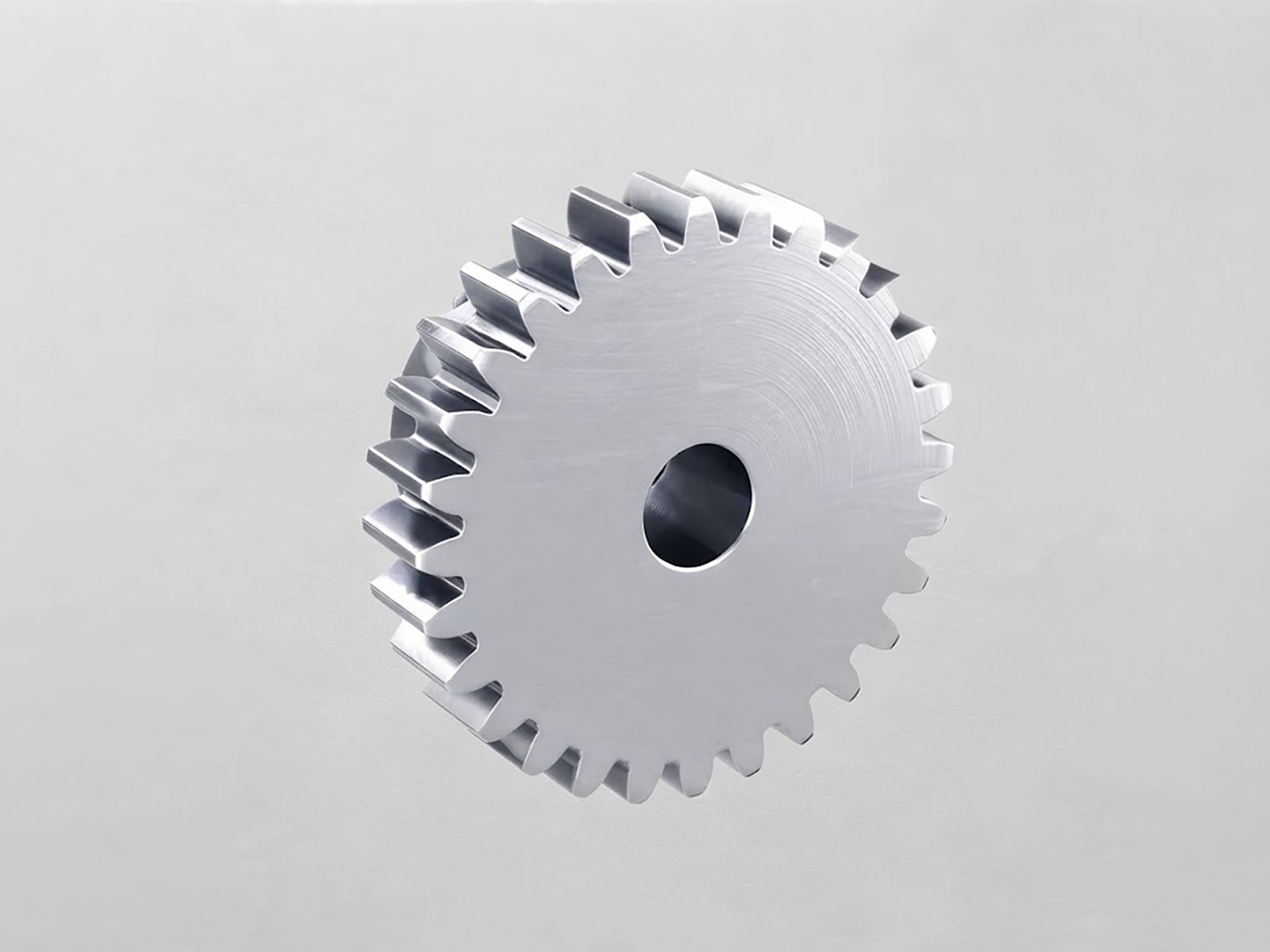
Define the starting condition before selecting the pinion
The starting condition should be a partially defined rotating assembly, not simply an outside diameter. Before calculating tooth load, confirm whether the gear is internal or external, whether it is integral with a bearing ring or supplied as a separate component, and whether the pinion position can be controlled under working load.
Use the following input list. Missing information does not always stop an initial quotation, but it does prevent a defensible tooth-load check. In particular, unknown torque, unknown pinion pitch diameter, or an unspecified tooth system blocks meaningful tangential-force evaluation.
| Required input | Why it affects the selection | What to provide | Can it be confirmed later? |
|---|---|---|---|
| Drive torque | It determines transmitted tangential force at the pinion pitch diameter. | Maximum operating torque, starting torque, braking torque, and any overload condition. | No. It is needed before tooth strength can be assessed. |
| Pinion geometry | Module, tooth count, pressure angle, profile, and face width must mate with the ring teeth. | Pinion drawing or a gearbox output drawing. | No. Do not assume a standard profile. |
| Ring geometry | The ring pitch diameter, tooth form, usable face width, and tooth direction govern engagement. | Ring drawing, tooth data, and internal or external gear position. | No for final release. |
| Duty cycle | Frequent starts, reversals, shock loads, and holding periods change the load case. | Rotation speed, starts per cycle, direction changes, and operating hours. | Partly, but define the highest-load duty first. |
| Mounting stiffness | Deflection can move the pinion out of its intended mesh and concentrate load at one tooth edge. | Drive bracket drawing, housing layout, and pinion support arrangement. | No for high-load equipment. |
| Environment | Contamination, corrosion, lubrication access, and temperature influence material and maintenance choices. | Installation location and lubrication method. | Yes for a preliminary design, but not before production release. |
For a geared bearing assembly, also state the axial load, radial load, overturning moment, and gear drive torque separately. Do not combine these figures into one “total load.” The bearing raceway and the gear teeth are checked by different methods. A bearing can have adequate rolling capacity while the gear teeth remain undersized for the selected motor and reducer.
LTZC supplies slewing bearings, gear rings, racks, bearing unit assemblies, and non standard bearing parts. Our design review can therefore consider the interface between the ring and the rotating support rather than treating the gear as an isolated purchased item.
Align tooth module face width pinion engagement and tangential force
To prevent tooth root overload, align four connected factors: tooth module, usable gear face width, pinion engagement, and tangential force. The correct conclusion is not “use the widest tooth” or “use the largest module.” The right combination depends on torque, available installation space, required rotation accuracy, and how consistently the drive bracket holds the pinion in mesh.
| Factor | Alignment action | Reasoning | Failure if ignored | Limit of the action |
|---|---|---|---|---|
| Gear tooth module | Specify the same module for ring and pinion and confirm the tooth system before machining. | Module establishes tooth size and pitch. Mismatched module prevents correct meshing. | High contact stress, noise, rapid wear, or inability to assemble. | Matching module alone does not confirm compatible pressure angle or tooth profile. |
| Gear face width | Compare the ring’s usable tooth width with the pinion face width and expected alignment movement. | Load should spread across the intended working width rather than a narrow edge band. | Edge loading and local tooth-root stress. | A wider pinion cannot correct a ring or mounting system that allows severe misalignment. |
| Pinion engagement | Set the design center distance and provide a controlled adjustment method for installation. | Correct engagement distributes force through the tooth flank and maintains suitable backlash. | Tooth tip contact, tight mesh, excess backlash, or one-sided wear. | Installation adjustment cannot compensate for an incorrect tooth form. |
| Tangential force | Calculate force from maximum torque and pinion pitch diameter, then use that force in the tooth-strength review. | The force at the pitch circle is what bends the tooth root and loads the tooth flank. | Undersized teeth, pinion failure, accelerated gear wear, or reducer overload. | A static calculation must be supplemented when shock, reversal, or braking loads occur. |
Use the following engineering sequence for transmitted load:
Identify the highest torque that can reach the pinion. Include startup, acceleration, braking, and externally induced torque where applicable.
Confirm the pinion pitch diameter from the selected module and tooth count.
Calculate tangential force with Ft = 2T / dp, where Ft is tangential force, T is transmitted torque, and dp is pinion pitch diameter. Keep units consistent.
Apply the relevant duty, dynamic, load-distribution, and tooth-strength factors specified by your chosen gear calculation standard.
Check the resulting tooth-root bending condition and tooth-flank contact condition for both the pinion and the ring teeth.
Review whether the actual engagement length remains inside the usable face width when the structure deflects under maximum load.
A smaller pinion pitch diameter increases tangential force for the same torque. This can be useful where space is limited, but it raises tooth loading and may increase sensitivity to installation error. A larger pinion reduces tangential force at the mesh, yet it may require a larger gearbox envelope and can conflict with nearby structures. Select the pinion diameter only after checking both gear force and physical clearance.
Do not use nominal face width as the full load-carrying width when the mounting bracket can flex. If the pinion shifts under load, only part of the tooth face may carry the force. The design check must use the effective engaged width supported by the assembly, not an optimistic full-width assumption.

Follow an executable selection sequence
1. Freeze the drive layout
Choose internal or external gearing, pinion location, reducer orientation, and access for lubrication before finalizing tooth dimensions. Successful progress means the pinion can be installed, adjusted, inspected, and lubricated without removing major machine components.
The common mistake is selecting a reducer first and forcing a pinion into the remaining space. That approach can lead to a pinion with an unsuitable pitch diameter or too little support stiffness. Revisit the drive layout if the pinion shaft cannot be supported close to the mesh point.
2. Match the tooth system exactly
Confirm module, pressure angle, tooth direction, profile, and tooth count. For helical designs, also confirm helix hand and helix angle. Ring and pinion drawings should identify the same tooth system. “Similar module” is not an acceptable release condition.
If the ring has modified teeth, ground teeth, or a specified backlash condition, supply that information with the pinion drawing. LTZC delivered a segmented gear ring, model US8.419.1606, with a 6 meter outer diameter and ground teeth for Hengshui customers. That case shows why tooth finish and the mating-pinion requirement should be identified in the technical package rather than added after machining.
3. Establish the allowable mesh position
Set the nominal center distance from the approved tooth data. Then design a practical adjustment arrangement, such as slotted mounting positions or controlled shimming, where the drive layout permits it. Adjustment is intended to establish the specified mesh condition during commissioning; it is not a substitute for rigid support.
At this point, define how backlash and contact pattern will be checked. Marking compound can reveal whether contact is centered across the gear face. A centered pattern indicates that the pinion is engaging the intended working area. A pattern concentrated near one edge indicates misalignment, shaft deflection, ring runout, or an incorrect mounting position.
4. Check the worst load case instead of the average load
Use the maximum credible torque condition for initial tooth-root assessment. A slowly rotating platform may still experience high loading during startup, emergency stopping, wind-induced movement, material impact, or reversal. Average motor torque is not enough where a gearbox can deliver a higher short-duration output torque.
The selection should also distinguish between continuous rotation and intermittent indexing. Continuous motion may create many load cycles. Intermittent motion can introduce high acceleration and braking peaks. Neither condition should be assumed to be easier without the actual motion profile.
5. Review the bearing and gear as one assembly
Gear mesh quality depends on the rotating ring staying within its intended position under axial load, radial load, and overturning moment. Select the bearing structure for the complete load case, then check whether ring deformation affects mesh alignment. For high-load layouts, compare options such as Three Row Roller Slewing Bearings where the application requires separate capacity for axial, radial, and overturning loads.
In 2024, LTZC delivered an integral three-row roller structure with a 10.87 meter outer diameter for 2,000 ton fixed lifting equipment. This documented project demonstrates experience with large integrated rotating structures. It does not remove the need to calculate each new application’s tooth load, pinion geometry, and support stiffness.
Verify completion through contact checks and load documentation
The selection is ready for release when the drawing package identifies the ring tooth data, pinion tooth data, nominal center distance, expected backlash requirement, calculated maximum tangential force, duty assumptions, lubrication approach, and mounting arrangement. A verbal statement that the pinion “matches” the ring is not enough for production or field commissioning.
Use this completion checklist before approving the geared assembly:
Ring and pinion module are identical.
Pressure angle and tooth profile are confirmed as compatible.
Helical tooth hand is confirmed when helical teeth are used.
Pinion face width works within the ring’s usable tooth width.
Maximum transmitted tangential force is calculated from the highest relevant torque condition.
Tooth-root and tooth-flank calculations use the selected gear design standard and applicable duty factors.
Pinion support and drive bracket stiffness are reviewed under working load.
Center-distance adjustment and inspection access are shown on the assembly drawing.
Lubrication points and contamination protection are defined.
Commissioning includes backlash and tooth contact pattern inspection.
If contact appears at one tooth edge during commissioning, do not attempt to solve the issue by increasing lubricant alone. First inspect the pinion mounting face, shaft support, reducer alignment, ring seating surfaces, and structural deflection. If the contact is centered but too close to the tooth tip or root, revisit center distance and tooth geometry. If contact is acceptable but tooth-root calculations fail, revise the module, effective face width, pinion pitch diameter, or transmitted torque assumption.
Follow the documented bearing installation process for mounting and inspection. LTZC provides installation guidance, preventive maintenance training, fault diagnosis, and on-site technical assistance. Quality objections receive a response within 24 hours, and on-site service in China starts within 48 hours.
Apply variations only when the application changes the load path
Large diameter, segmented, or high-load installations require additional attention to ring support and local gear alignment. Segment joints, mounting flatness, and structural stiffness can affect the contact pattern around the circumference. Do not assume that a pinion setting measured in one position remains identical at every angular position.
For equipment that must resist corrosion, temperature exposure, or special operating conditions, material selection should be reviewed separately from tooth geometry. LTZC can provide customized bearing solutions based on working conditions, existing designs, and technical specifications. The facility operates under ISO9001:2015, ISO14001:2015, and ISO45001:2018 systems and is certified by ISO, CCS, and ABS.
When the assembly is non standard, provide the ring drawing, pinion drawing, reducer output torque, duty cycle, mounting concept, and required delivery date together. LTZC offers no MOQ and typical delivery is 30 to 90 days, subject to the design and order requirements. Submit your drawings for gear matching advice and a technical quotation.