WhatsApp
 jessica.chai@ltzzc.com
 0086-379-69950051

Slewing Bearing Installation Starts With Alignment Before Bolt Tightening
A bearing passes incoming inspection, goes onto the structure, and turns roughly after the last bolt is torqued. Where did the damage happen? Usually at the moment the bolts pulled a ring onto a surface that was not truly flat or concentric. This guide covers that moment. It walks through slewing bearing installation up to the point where you apply final torque, so you can check alignment while the ring can still be corrected. For the wider maintenance routine around it, see our page on bearing installation.
The sequence suits maintenance engineers and equipment assemblers fitting a new precision slewing bearing to a crane, turntable, or similar machine. Your starting state: the bearing is unpacked, the mating structure is in place, and no bolt has been tightened. The finish state: the ring sits without gaps, the marked soft zone is positioned, the gear mesh is verified, and you are ready for staged bolt tightening.
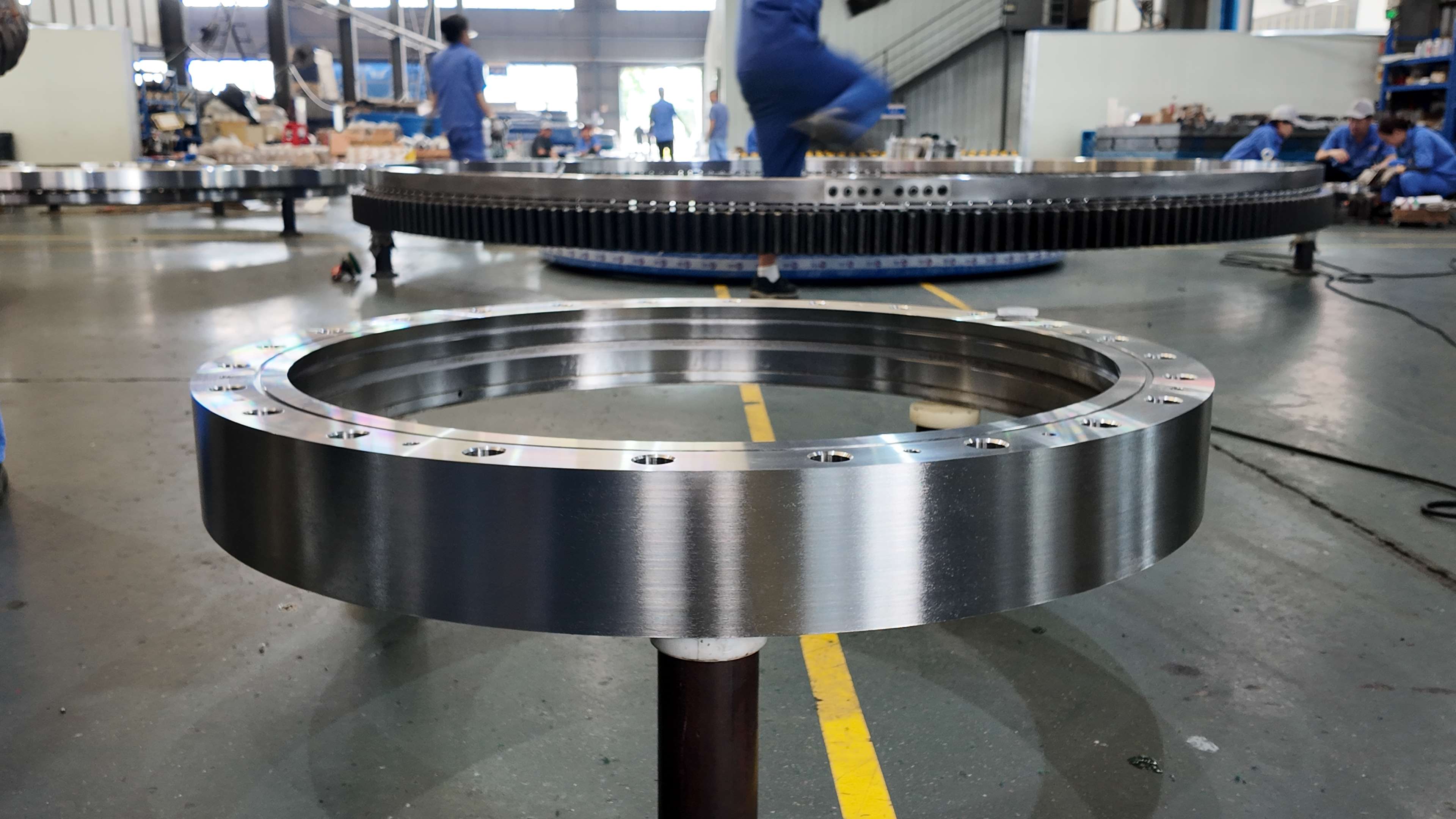
What You Need Before the Bearing Touches the Structure
Some missing items stop the job. Others can be settled later. Sort them first.
Blocking items: do not proceed without these
The mounting drawing and bolt specification. It gives bolt grade, size, count, and the tightening value. Never guess torque. If the drawing is missing, ask the bearing supplier before assembly, not after.
Flatness and runout limits for the mounting faces. These come from the drawing or the manufacturer's installation instructions. We do not quote one universal figure here, because the allowable value depends on bearing diameter, section height, and raceway type.
A way to measure flatness. Use a straightedge with feeler gauges, or a dial indicator on a magnetic base that can sweep the full circumference.
Lifting gear that keeps the ring level. A ring that hangs tilted will scrape the structure on landing and drag debris across the seat.
A calibrated torque wrench or tensioning tool suited to the bolt size.
Items you can clarify later
The exact grease brand for the first fill, as long as it is confirmed before commissioning.
The long-term re-torque interval, which belongs in your maintenance plan rather than the fitting step.
Also inspect the bearing itself. Find the soft-zone marker on the ring, usually a stamped letter or symbol at the quench gap. Note which ring carries the gear. Wipe off the rust-preventive coating from the mounting faces only; leave raceways and seals alone.
How Alignment Checks Prevent Raceway Distortion and Uneven Bolt Loading
A slewing bearing is a thin ring compared with its diameter. It does not impose its own shape on the structure. The structure imposes its shape on the ring. Tightening bolts onto an uneven seat bends the ring toward the low spots, and the raceway bends with it. That raceway distortion causes high rolling-element loads at certain points, tight spots in rotation, and early fatigue. Alignment checks before tightening expose the problem while it can still be shimmed, machined, or re-seated.
| Pre-tightening check | What it detects | What happens if skipped |
|---|---|---|
| Feeler gauge gap between ring and seat | Local low spots, warped plate, weld distortion | Bolts pull the ring down into the gap and bend the raceway |
| Dial indicator sweep of the seat face | Overall flatness error and tilt | Load concentrates on the high side; bolts there carry more than their share |
| Radial centering against the spigot or pilot diameter | Offset between bearing and structure axis | Bolt holes pull sideways, bolts see shear, gear mesh becomes uneven |
| Soft-zone marker position | Hardened-gap location relative to the main load direction | Peak load runs across the unhardened section and shortens raceway life |
| Gear backlash check at several points | Eccentric mounting or tooth runout | Tight mesh at one angle, excess backlash at another, uneven tooth wear |
| Hand or drive rotation before final torque | Binding caused by early distortion | You discover the fault only after all bolts are loaded and rework is expensive |
Uneven bolt loading follows from the same causes. If one section of the ring is held off the seat by a gap, the bolts in that section stretch more while tightening and then relax under working load. Bolts on the high side stay overloaded. Neither group reaches the clamp load the drawing assumes.
Step-by-Step Alignment Sequence
Clean and inspect both mounting faces. Remove paint lumps, weld spatter, burrs, and dust. Run a flat stone lightly over bolt-hole edges. Checkpoint: a clean hand wipe leaves no grit, and no raised metal is felt at hole edges.
Measure the empty seat before the bearing arrives on it. Sweep a dial indicator around the full circumference, or place a straightedge across the seat in at least four directions with feeler gauges beneath. Record the readings against the drawing limit. Checkpoint: every reading is within the limit. If not, stop; correct the seat by machining or shimming before going further. Shimming only works if shims carry full contact area.
Mark the soft zone and decide its position. Place the marker where the drawing specifies, generally away from the main load zone and clear of the most heavily loaded sector. Mark it on the structure with a paint pen so the position is visible from the ground.
Lower the bearing level and seat it. Lower it slowly, with a lifting method that keeps the ring level. Do not drag it across the seat. Checkpoint: the ring sits without rocking when pressed lightly at opposite points.
Check for gaps. Slide a feeler gauge around the contact line between ring and seat, and record any gap by clock position. Checkpoint: no gap beyond what the drawing allows. A visible gap means the bolts will bend the ring, so cure it before tightening.
Center the bearing. Use the spigot or pilot diameter if the design has one. Otherwise, use dial indicator readings on the inner or outer diameter at four points. Insert alignment pins or a few fitted bolts through opposite holes to hold position.
Fit the pinion and check backlash. If the bearing is geared, mesh the pinion and measure backlash at four to eight positions around the ring, always at the same pinion position. Check the tightest point against the manufacturer's value. This is when eccentric mounting shows itself.
Install all bolts finger-tight. Use the specified grade, washers, and thread lubricant as stated on the drawing. Do not reuse bolts the drawing marks as single-use. Checkpoint: every bolt threads in by hand without forcing.
Tighten in stages, in a cross pattern. Bring all bolts up evenly in passes, working diagonally across the ring, then repeat each pass at a higher value until the specified final torque. After the first pass, rotate the bearing by hand or by drive if possible and feel for binding. Checkpoint: rotation stays smooth between passes. If it begins to bind after a pass, loosen and go back to step 5.
Final verification pass. Re-check the final torque on every bolt after a full rotation of the bearing, since bolts relax slightly as neighbors tighten.
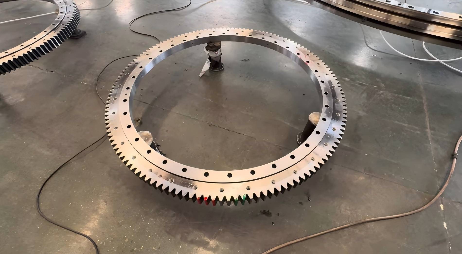
Common Mistakes and What They Look Like
| Mistake | Observable effect | Recovery |
|---|---|---|
| Tightening one side fully, then moving on | Ring tilts; gaps open opposite; bearing binds at one angle | Loosen all bolts, re-seat, restart in staged passes |
| Skipping the empty-seat measurement | Rough rotation and gap readings that vary around the circumference | Remove the bearing and correct the seat; do not shim over a warped plate without checking contact area |
| Soft zone placed in the main load sector | No immediate symptom; raceway wear appears earlier than expected | Rotate the ring to the correct position before tightening; after tightening it means a full removal |
| Checking gear backlash at one position only | Tight mesh at another angle after commissioning | Measure at multiple positions, then re-center the ring |
| Mixing bolt grades or reusing single-use bolts | Clamp load differs bolt to bolt; some bolts loosen in service | Replace the full set with bolts to the drawing specification |
| Welding near the bearing after fitting | Heat distortion and possible raceway damage | Complete all welding before the bearing is on the structure |
Completion Check and Recovery
Use this checklist before you call the job done:
Seat flatness readings are recorded and inside the drawing limit.
No gap between the ring and seat beyond the drawing allowance.
Soft-zone marker position is recorded and matches the specification.
Backlash measured at several positions, with no tight point beyond the stated value.
All bolts reached final torque in staged cross-pattern passes, then rechecked after a full rotation.
Rotation is smooth through 360 degrees with no tight spots.
If rotation binds, revisit step 5 first (gaps), then step 2 (seat flatness). If the backlash varies around the ring, revisit step 6 (centering). If bolts lose torque on the recheck pass, suspect uneven seating or wrong bolt grade rather than simply tightening again.
Our after-sales team supports installation guidance and fault diagnosis. We respond to quality objections within 24 hours and start on-site service within 48 hours in China. That support does not replace your own checks. It gives you a route if readings do not agree with the drawing.
Variations That Change the Procedure
Very large diameters. A Large Slewing Bearing flexes more under its own weight and follows the seat shape closely. We have delivered an integral three-row roller ring with a 10.87 m outer diameter in 2024, and an 8.445 m integrated bearing for a crane client in South Korea. At that scale, measure the seat at more points and plan for additional personnel, since torquing sequence takes longer and the ring should not sit partly bolted for long.
Segmented rings. A Split Slewing Bearing needs joint faces aligned and joint bolts tightened per the drawing before the mounting bolts. We have supplied φ24 m segmented bearings to Jiangsu Nantong Rainbow Heavy Machinery, so this is a design where the joint check comes first.
Roller-type designs. Three Row Roller Slewing Bearings carry heavy loads and are less forgiving of tilt, so gap and flatness checks matter more than usual.
Separate gear rings. When the gear is supplied as a separate slewing ring gear, check its seat and centering separately from the bearing.
If you are still choosing a bearing type for the job, our bearing selection guide covers load cases and structure types. LTZC operates under an ISO9001:2015 quality management system, and our engineering team can review your mounting drawing before parts are made. To get installation advice for your bearing, send us the mounting drawing and bolt specification, and we will confirm the alignment checks suited to your structure.