WhatsApp
 jessica.chai@ltzzc.com
 0086-379-69950051

How to Size a Large Slewing Bearing for Combined Loads
A slewing bearing never sees one load at a time. Axial force, radial force and tilting moment arrive together, and the moment usually decides the size. So how do you turn three load values and a duty cycle into a bearing diameter and raceway type? This guide gives a practical sequence for engineers sizing a Large Slewing Bearing for a crane, excavator or other heavy machine before requesting quotations. If your machine is still at concept stage, our bearing selection guide covers the wider product choices, and the precision slewing bearing range shows the structures discussed below.
What "combined load" means for the sizing decision
The short answer: size on the moment first, the axial load second, and treat radial load as a check. The moment acts across the full raceway diameter and concentrates contact stress on one side of the bearing. Axial load spreads more evenly. Radial load is typically the smallest component on cranes and excavators, but it can limit ball-type bearings and bolt joints.
- Axial load (Fa): vertical load including payload, boom and structure self-weight, and dynamic factors.
- Radial load (Fr): horizontal force from wind, side pull, slewing inertia or digging reaction.
- Moment (M): load multiplied by its offset from the bearing axis, plus any horizontal force multiplied by its height above the raceway.
This applies when the bearing carries a structure on a fixed or slewing platform. It does not cover bearings that spin continuously at speed, where a different rating method is needed.

Turning an axial-radial-moment load spectrum into a sizing sequence
Rating catalogues show a static limiting load curve and, for some designs, a fatigue life reference. Your job is to place a correctly built load point under that curve. The sequence below is how we suggest organising inputs before any quotation request.
| Step | Input or action | Why it matters |
|---|---|---|
| 1 | List every load case: working, maximum working, out-of-service wind, test load, erection | The governing case is often not the rated working case. |
| 2 | For each case, record Fa, Fr and M at the bearing centre plane | Loads measured at the boom foot or a column base must be moved to the bearing plane, or the moment will be wrong. |
| 3 | Add dynamic factors for hoisting, braking, slewing acceleration and shock | Static values understate what the raceway sees during start-stop cycles. |
| 4 | Apply the safety factor required by your governing crane or machinery standard and application class | The factor depends on duty class and consequence of failure; do not borrow one from a different machine type. |
| 5 | Plot each factored load point on the manufacturer's static limiting load curve for the candidate type and size | Every point must sit under the curve, not just the working case. |
| 6 | Build the duty cycle: share of time at each load level, plus slewing angle or number of rotations | Needed for the fatigue check and for deciding how much of the raceway is actually loaded. |
| 7 | Check bolts, mounting structure stiffness and gear loads separately | A bearing rated for the load can still fail through a flexible seat or overloaded bolts. |
How the key parameters interact
| Parameter | What it changes | Common misreading |
|---|---|---|
| Moment (M) | Peak contact load on the loaded side of the raceway; scales with 1/D | Treating it as a minor add-on to axial load. |
| Raceway diameter (D) | A larger D cuts the edge load from a given moment, but raises weight, cost and mounting-structure size | Assuming the biggest bearing is automatically the safest choice. |
| Axial load (Fa) | Sets baseline preload on all rolling elements and offsets part of the moment effect | Using self-weight only and ignoring dynamic additions. |
| Radial load (Fr) | Loads the raceway shoulder and the bolts; limited by the radial-to-axial ratio the design permits | Ignoring it because the value looks small beside Fa. |
| Duty cycle | Determines fatigue exposure, which can govern even when the static check passes | Sizing only on the maximum static case. |
| Safety factor | Scales every load before plotting; varies with application class | Using one factor for every machine. |
Worked example: why moment drives the diameter
The numbers below are illustrative only, not a rated selection. Take a pedestal crane with a bearing raceway diameter of about 2.0 m, carrying Fa = 500 kN, Fr = 50 kN and M = 1,500 kN·m in the governing load case.
- Estimate the moment's contribution to peak axial edge load with a simple force-couple approximation: 2M / D = 2 × 1,500 / 2.0 = 1,500 kN.
- That is three times the 500 kN axial load. The bearing is moment-dominated, so sizing on Fa alone would undersize it.
- The radial ratio Fr/Fa is 0.1. This is low, but still compare it with the permitted ratio for the chosen type.
- Apply the standard-required safety factor and dynamic factor, then plot the point on the static limiting load curve of a candidate.
- If the point is near the curve edge, increase raceway diameter or change the structure type. Do not only add bolts.
The approximation is coarse; the manufacturer's rating method replaces it for final selection. Its value is early screening, so you can see which load component dominates before you ask for quotations.
Choosing the bearing type once the load ratio is known
Type follows load ratio, stiffness need and available space. The comparison below is qualitative; final capacity comes from the rating curves for the specific size.
| Type | Typically suits | Trade-off |
|---|---|---|
| Single Row Ball Slewing Bearings | Moderate loads, compact sections | Lower moment capacity per section height than roller types. |
| Double Row Ball Slewing Bearing | Higher axial and moment loads where a ball design is preferred | Wider section and more mounting height. |
| Cross Roller Slewing Bearings | Stiffness and rotational accuracy in compact sections | Mounting surfaces must be flatter and stiffer. |
| Three Row Roller Slewing Bearings | Heavy axial and moment loads; large cranes and lifting equipment | Larger and heavier; requires rigid structure and careful installation. |
A Crane Slewing Bearing usually leans toward the heavier rows because lifted-load moment dominates. An excavator sees shock and side load, so radial check and bolt joint design deserve more attention there. Where a standard catalogue size does not match your envelope or load spectrum, Customized Bearings built to your drawings are an option.
Common mistakes in combined-load sizing
- Using working load only. Out-of-service wind or test load often governs the static check.
- Reading loads at the wrong plane. A moment taken at the boom foot is not the moment at the bearing plane.
- Skipping dynamic factors. Braking and slewing acceleration add real load; leaving them out understates every point.
- Choosing diameter from the catalogue's smallest passing size. A point just under the curve leaves no room for tolerance, wear or structure deflection.
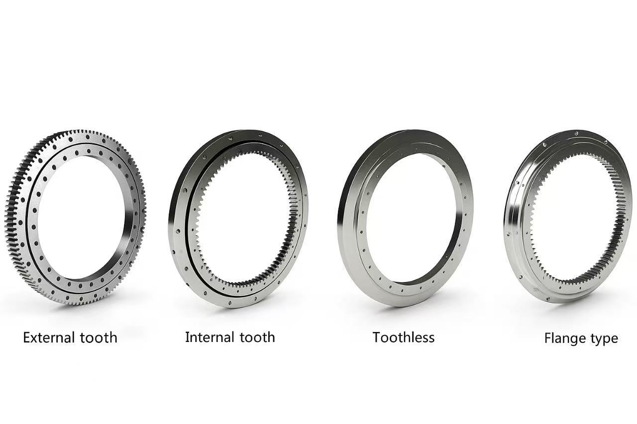
- Treating the gear as an afterthought. Tangential tooth force is another load path; discuss the slewing ring gear specification together with the bearing.
- Comparing ratings from different methods as equal. Static limiting curves and fatigue life figures are not interchangeable.
What to verify beyond the rating curve
A passing load point does not prove the installation will work. Ask for evidence on these items:
- Mounting structure stiffness: a flexible seat distorts raceways and shortens life. Flatness requirements should be agreed before drawings are frozen.
- Bolt joint: bolt count, grade and preload need their own check against the same factored loads.
- Gear geometry and load: module, face width and heat treatment need to match the drive torque and shock level.
- Material and heat treatment records: LTZC works with materials such as 42CrMo and 20CrMo for heavy loads and GCr15 or SUJ2 for high-hardness raceway applications. Ask which applies to your size and why.
- Installation method: follow written bearing installation guidance, including bolt tightening sequence and clearance checks.
Real reference points for very large sizes
Size changes how a bearing is made and shipped, not just how it is rated. In 2024 LTZC delivered a slewing ring with an outer diameter of 10.87 meters, an integral three-row roller structure for 2,000 ton fixed lifting equipment. This is the largest slewing ring we have produced. That same year we completed an integrated bearing with an outer diameter of 8.445 meters for a crane-industry client in South Korea. We have also developed φ24 m segmented bearings delivered to Jiangsu Nantong Rainbow Heavy Machinery, a case where splitting the ring was part of the engineering answer. These are individual projects, not a standard lead time or capacity promise for every order.
On the quality side, our facility holds ISO9001:2015, ISO14001:2015 and ISO45001:2018 certification, with certification by ISO, CCS and ABS. We have worked since 1992 and operate on a 20,000 m² site. Orders have no MOQ and delivery runs 30-90 days depending on size and specification. After delivery, customer quality objections receive a response within 24 hours, and on-site service in China starts within 48 hours. Jessica Chai, a slewing bearing engineer with 10 years in slewing bearing, slew drive and thin section bearing sales and service, often reviews these inputs with customers at this stage.
Checklist to send before requesting a quotation
- Load cases with Fa, Fr and M, and the plane at which each was calculated
- Dynamic factors used and the standard or application class governing the safety factor
- Duty cycle: load shares, slewing angle or rotations, operating temperature and environment
- Envelope: maximum outer diameter, inner diameter, height and bolt circle
- Gear requirement: internal or external, module, tooth hardening, drive torque
- Mounting structure drawings or flatness capability
- Preferred type, if any, and whether a split or segmented design is acceptable for transport
Send your load table and envelope drawings to LTZC engineering for selection advice, or ask for a technical review of an existing design. We will point out missing inputs before quoting, instead of guessing a final size.