WhatsApp
 jessica.chai@ltzzc.com
 0086-379-69950051

Slewing Bearing Maintenance for Bolt Torque Warning Signs
When does a bolt torque issue require a routine recheck, a mounting-interface inspection, or an equipment stop? For reliability engineers and maintenance supervisors, the answer is not found by looking at one bolt alone. The useful evidence is the relationship between bolt movement, joint separation, torque-check results, and whether preload loss returns after corrective action.
Slewing Bearing Maintenance should treat the bolted connection as a structural system. A slewing ring transfers overturning moment, axial load, radial load, and operating vibration through its raceways and mounting rings into the machine structure. If the mounting connection loses clamping force, the bearing may move relative to the frame or rotating structure. That movement can enlarge bolt holes, damage mounting faces, change gear mesh, and eventually create structural damage that a simple re-torque cannot correct.
The first rule is straightforward: a bolt that is below the specified tightening condition is a warning, but recurring loss of bolt preload is evidence that the complete joint needs investigation. Do not assume that a torque wrench reading alone proves the joint is sound. Torque is an indirect indication of bolt tension because friction, thread condition, lubrication condition, seating surfaces, and fastener condition all influence the result.
Before setting up an inspection plan, confirm the bearing arrangement and machine duty. A precision slewing bearing installed on a slow-turning crane has different load patterns from an Excavator slewing bearing exposed to repeated shock loading. The approved bolt specification, tightening sequence, lubrication instructions, and inspection criteria supplied for the actual machine always take priority. For installation records and mounting practices, review the supplier’s bearing installation guidance before applying any corrective work.
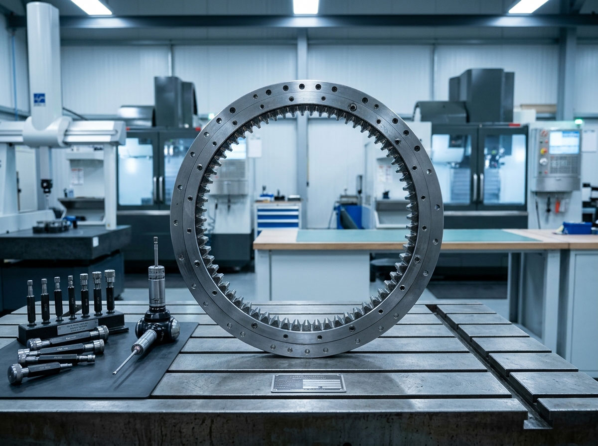
Classify the warning before choosing the response
A torque warning can range from normal early seating behavior to an indication of mounting-face damage. The response should match the evidence. Retightening every bolt without identifying the reason for looseness can hide the developing fault for one inspection cycle while the interface continues to deteriorate.
| Observed condition | Likely interpretation | Recommended response | Limit of the conclusion |
|---|---|---|---|
| One isolated bolt shows a different torque-check result, with no visible movement or gap. | The issue may be local to the bolt, thread, washer, lubrication state, or previous tightening practice. | Inspect the bolt and mating threads according to the approved service procedure. Check adjacent bolts and document the location. | One reading does not prove that the bearing ring or mounting face is damaged. |
| Several adjacent bolts require correction in the same loaded zone. | Localized joint settlement, ring movement, surface irregularity, or repeated load concentration may be involved. | Expand the inspection beyond the affected bolts. Check for movement marks, joint-gap evidence, mounting-face condition, and local structure distortion. | The pattern must be compared with the machine’s operating position and load direction. |
| Torque loss returns after bolts are corrected using the approved procedure. | The joint may not be maintaining preload. Repeated seating, bearing-ring movement, interface compression, or incorrect assembly conditions are possible. | Escalate to a mounting-interface inspection and obtain engineering review before repeated re-torque becomes routine. | Do not assign a single root cause until the joint faces, fasteners, and operating history are checked. |
| Visible ring movement, fretting debris, paint disruption, a measurable gap, cracks, or damaged bolt holes. | The connection may have lost structural integrity. | Remove the equipment from service in accordance with site safety procedures and seek qualified engineering assessment. | Safe shutdown steps depend on the machine, suspended-load risk, stored energy, and site rules. |
The practical distinction is this: a single abnormal fastener can be a fastener-level issue; a repeating pattern or physical movement is a joint-level issue. This distinction matters most on heavily loaded equipment such as cranes, excavators, stacker-reclaimers, and large turning platforms.
For example, a crane bearing can experience changing overturning moment as the boom position changes. If warning signs occur repeatedly in the same sector, record the ring-clock position and correlate it with boom direction, load condition, and parking position. A random-looking torque check without position data may miss the relationship between the observed bolt condition and the machine load path.
How bolt preload, surface contact, and operating load interact
Mounting bolts do more than hold the bearing in place. Their preload clamps the bearing ring to its support structure. When clamping force is correct, the joint faces remain in close contact and operational loads are shared through the mounted structure as intended. When preload falls, the parts can microslip under cyclic load. That small relative movement can become a larger problem.
What bolt movement changes in practice
Bolt rotation or backing-off marks: These indicate possible loss of resistance to rotation or movement in the joint. Inspect witness marks, locking features, thread condition, and the local mounting area. A mark alone does not establish the reason for preload loss.
Fretting debris around the ring or bolt locations: Fine dark or reddish debris may indicate repeated micro-movement between contact surfaces. Treat it as a reason to inspect the joint face rather than merely clean the area and retighten.
Shiny rubbed areas or disrupted paint: These can show relative motion between the bearing ring and support structure. The finding fits a mounting-interface review, especially if it appears near multiple fasteners.
Elongated bolt holes or damaged threads: These indicate that movement has progressed beyond normal seating. Continued operation can place unintended shear and bending demands on fasteners. Isolate the machine according to the applicable safety process and seek engineering direction.
Why a joint gap changes the urgency
A joint gap is more serious than a bolt that merely needs a torque correction. It means the bearing ring and mounting structure may not be sharing contact as intended. The cause may involve dirt trapped during assembly, uneven support faces, local deformation, settlement, coating buildup, corrosion products, or distortion under operating load. Each cause requires a different repair decision.
Do not use a gap observation to declare that the bearing itself has failed. The gap may originate in the supporting structure rather than the raceway assembly. Conversely, do not assume the supporting frame is acceptable because the bearing still turns. Rotation can continue while the mounting interface is deteriorating.
Why torque checks must be controlled
A torque wrench measures turning resistance, not direct bolt tension. The same wrench setting can produce different clamping force when thread lubrication, washer condition, corrosion, or surface finish changes. Therefore, a meaningful check needs a controlled method: the correct tool, the approved tightening sequence, known fastener condition, and a record of location and result.
The correct conclusion is not “higher torque is safer.” Excess tightening may damage threads, overstress fasteners, or distort the mounted components. Use only the bolt grade, tightening requirement, and sequence specified by the machine or bearing supplier. If those requirements are unavailable, stop short of making field assumptions and request the relevant technical documentation.
Condition monitoring links bolt movement to mounting-interface faults
The most useful condition-monitoring approach combines four evidence streams: bolt movement, joint-gap evidence, torque-check results, and recurring preload loss. None should be interpreted in isolation. Together, they help separate a simple fastener concern from a developing mounting-interface fault.
| Evidence to monitor | What it can indicate | How it interacts with other findings | Action decision |
|---|---|---|---|
| Bolt-head witness marks, changed locking position, or visible movement | Possible rotation, local joint movement, or loss of clamping stability | If movement is paired with repeated torque loss, suspect that the joint is not retaining preload rather than assuming an isolated loose bolt. | Inspect the bolt group and document affected ring positions. |
| Fretting, rubbed paint, corrosion staining, or visible separation at the interface | Relative movement or incomplete contact between the ring and support | If interface evidence occurs with low torque-check results, the mounting face requires more attention than the fastener alone. | Escalate to inspection of ring seating and support structure. |
| Torque-check results outside the approved acceptance condition | Possible preload variation, but not direct proof of actual bolt tension | If the result is isolated and no movement exists, inspect the individual fastening condition first. If clustered, assess the local interface. | Correct only through the approved procedure and record every location. |
| Recurring preload loss after approved corrective tightening | A continuing cause such as settlement, interface damage, deformation, or repeated movement | When recurrence appears with a gap or fretting, repeated re-torque is not an adequate final action. | Arrange engineering review and consider removing equipment from service based on risk assessment. |
This approach changes the maintenance question from “Which bolt is loose?” to “Why is the bolted joint losing its ability to clamp?” That is the right question when the same location keeps returning on maintenance reports.
A useful inspection record should include the bearing identification, ring-clock position, bolt location, tool used, observed condition, torque-check outcome, evidence of movement, operating position, load condition if known, and action taken. Photographs taken from the same orientation at each inspection make paint disruption, fretting, and gap progression easier to compare.
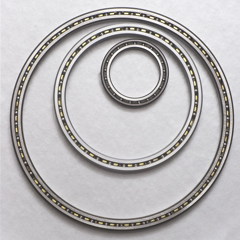
Use a repeatable inspection procedure instead of a one-time torque survey
A one-time survey can identify an obvious problem, but trendable inspections are better for finding early deterioration. The procedure below is suited to planned maintenance work. It does not replace the machine manufacturer’s safety rules, lifting controls, lockout requirements, or bearing supplier instructions.
Make the machine safe. Park, isolate energy sources, control suspended-load hazards, and follow the site’s approved maintenance process before accessing the bearing connection.
Identify the inspection reference. Mark a fixed ring-clock reference point on the stationary structure and use it on every inspection record. This prevents findings from being reported only as “left side” or “rear,” which can change with machine orientation.
Clean only enough to inspect. Remove loose contamination that hides bolt heads and joint edges. Do not remove evidence such as fretting residue before it has been photographed and recorded.
Inspect the complete accessible circumference. Look for bolt-head movement marks, missing or damaged locking features, washer damage, paint disturbance, corrosion, fretting, local gaps, cracking, and damaged bolt-hole areas.
Map findings by position. Record every abnormal point by ring-clock position. Grouped findings are more informative than a total count of bolts requiring attention.
Perform checks using the approved method. Use the specified tool, tightening sequence, and acceptance criteria. Do not substitute a generic torque value or apply extra torque as a precaution.
Compare against prior records. Determine whether the same bolts, sectors, or interface locations repeat. Recurrence is the main escalation trigger.
Choose corrective scope. An isolated condition may support local fastener inspection. Clustered or recurring findings support a wider mounting-interface assessment. Visible structural damage requires a safety-led response before return to service.
The limits matter. This procedure can reveal a pattern, but it cannot confirm support-frame flatness, hidden cracking, internal raceway damage, or correct bolt tension without the appropriate engineering methods and access. Use it to decide what evidence must be collected next.
Common mistakes that turn a manageable warning into a larger repair
Retorquing without recording location: This loses the pattern. A repeating problem at one sector can point to a load path or local interface issue that a whole-ring average hides.
Treating all low readings as identical: An isolated bolt and a cluster of adjacent bolts have different implications. Check whether the warning follows load direction, operating position, or a visible mounting condition.
Ignoring fretting because there is no obvious crack: Fretting is physical evidence of relative movement. It should trigger review of contact surfaces and clamp retention.
Increasing tightening force without the approved specification: More torque does not automatically mean better preload. It may create a different fastener or structural problem.
Replacing only the visible damaged bolt: If hole damage, ring movement, or recurring preload loss is present, the adjacent fastening group and mounting face also need assessment.
Mixing fastener conditions during maintenance: Differences in lubrication, corrosion state, washers, or thread condition can make torque comparisons misleading. Maintain the approved assembly condition and document any deviation.
Assuming the bearing is the only possible cause: The bearing, support frame, rotating structure, gear engagement, and bolt system work together. Inspect the interface before assigning the fault to one component.
Apply escalation criteria to the equipment duty and bearing design
Inspection findings must be considered with equipment duty. A bearing on a high-load lifting machine can experience concentrated loading in predictable positions. In contrast, a continuously rotating process machine may distribute duty more evenly but can accumulate repeated vibration cycles. The same visual evidence may therefore require different review of operating history.
For heavy lifting applications, bearing type and support stiffness deserve attention because overturning moment can strongly affect ring seating. LTZC has supplied an integrated three-row roller slewing ring with an outer diameter of 10.87 meters for 2,000 ton fixed lifting equipment. This type of application illustrates why large-diameter connections require disciplined inspection records and mounting-interface control; it does not establish a universal inspection interval or torque requirement for other equipment.
Where the application uses a multi-row roller arrangement, review the relevant Three Row Roller Slewing Bearings configuration alongside the actual load cases and support design. For systems where gear mesh is also affected by ring movement, inspect the associated slewing ring gear for abnormal contact indications after the bolted joint has been assessed. Do not adjust gear engagement to mask a bearing-ring mounting problem.
LTZC Bearings Co., Ltd. operates from a 20,000 m² facility established in 1992 and holds ISO9001:2015, ISO14001:2015, and ISO45001:2018 certifications, with ISO, CCS, and ABS certification stated by the company. For non-standard equipment, we can review working conditions, existing designs, drawings, material needs, dimensions, and performance requirements for customized bearing solutions. This is useful when an inspection finds that the original mounting arrangement needs technical review rather than another routine bolt correction.
Prepare the evidence needed for an engineering decision
Before requesting support, assemble facts that allow a bearing or structural engineer to distinguish between a bolt issue and an interface issue. The most useful package is practical and focused:
Bearing drawing or identification details, including internal or external gear arrangement where relevant.
Machine type, duty description, typical operating positions, and the load condition when the warning was found.
Photos of bolt heads, washers, joint edges, fretting evidence, cracks, and affected sectors, each marked with ring-clock position.
The approved bolt specification, tightening sequence, tool method, and records from current and previous checks.
A map showing which locations required correction and whether the same locations have repeated.
Details of any recent bearing replacement, structural repair, repainting, bolt replacement, or gear adjustment.
This information supports a better decision: routine correction when evidence remains isolated, expanded inspection when findings cluster, and immediate safety action when physical movement or structural damage is present. It also avoids the costly mistake of ordering parts before the mounting condition has been established.
Submit your bearing drawing, bolt-inspection record, and site photos to LTZC for application-specific mounting and maintenance advice.